Legrand HA5000-xx User Manual
Instruction / installation sheet lcd console, Is-0390 rev. a
INSTRUCTION / INSTALLATION SHEET
LCD Console
IS-0390 Rev. A
©Copyright 2010 by Legrand All Rights Reserved.
Page 1 of 3
301 Fulling Mill Road, Suite G
Middletown, PA 17057
Phone (800) 321-2343 / Fax (717) 702-2546
www.onqlegrand.com
1. INTRODUCTION
The Legrand LCD Console (P/N HA5000-xx) provides a large, easy-to-operate display from which a
homeowner can monitor up to four different cameras in different places throughout the home (see Figure 1).
When paired with the Legrand Integration Module (P/N HA6001), as part of a Unity System, the HA5000 LCD
Console can function as a user interface and a Selective Call Intercom Room station.
2. FEATURES
The LCD Console features:
• Large 7" LCD screen with adjustable color, contrast and brightness
• One-wire installation: Receives power, video, and audio from CM1010 LCD Module (available
separately) or from HA6001 Unity Integration Module (also available separately) over a single Cat 5
cable
• Backlit keys for easy navigation
• Integrated speaker with adjustable audio level with mute capability
• Four Quick-Menu buttons for easy viewing of up to four different cameras or other audio/visual sources
• Integrated sequencer display capability
• IR receiver window supporting full Remote Control operation of the LCD Console
• Adjustable automatic power-off timeout
• Functions as a Selective Call Intercom Room station (requires use with HA6001 Integration Module as part of Unity System)
3. INSTALLATION
NOTE: The LCD Module (P/N CM1010) provides power, audio, and video to the LCD
Console. The LCD Module can operate up to four LCD Consoles; repeat the
procedure below for each LCD Console to be installed.
A. At the selected LCD Console location, install a plastic triple-gang box like the Slater®
P3-54-RACMH or equivalent.
B. Home-run a single Cat 5e cable from the LCD Console location to the enclosure
location where the LCD Module resides.
NOTE: Leave extra cable at each end. At the LCD Console location, feed the
cable into the lower left corner of the gang box then pull it through (see Figure
3). At the enclosure end, route the cable through the enclosure, enough so the
cable reaches the LCD Module without stretching.
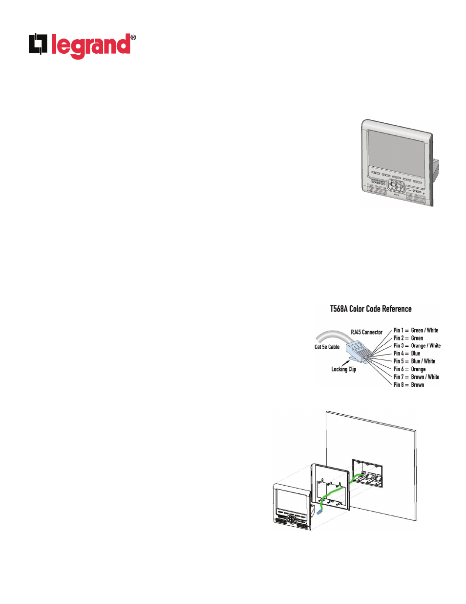
C. Terminate both ends of the Cat 5e cable from the LCD Console to the LCD Module
using RJ45 Plugs, according to the T568A wiring standard (see Figure 2).
D. At the LCD Console location, use the included screws to fasten
the display mounting bracket to the gang box.
IMPORTANT: Pull the cable coming through the lower left corner
of the gang box through the opening in the mounting bracket
prior to fastening the bracket to the box (see Figure 3).
E. Insert the RJ-45 plug at the LCD Console into the RJ-45 jack located
on the rear of the LCD Console.
F. Feed any excess cable back into the wall.
G. Push the left side of the LCD Console into the mounting bracket until
it is flush with the inside-back left side of the bracket, then snap it in
by pushing on the right side.
NOTE: To remove the LCD Console from the bracket, simply slide
a credit card or guitar pick along either the right-hand or left-hand
edge of the LCD Console to detach the retaining clips.
H. At the enclosure location, insert the RJ45 plug from the LCD Console
location into an available RJ45 output jack on the LCD Module.
I. Apply power to the LCD Module, and test for LED illumination at
the LCD Console.
Figure 1
Figure 2
Figure 3