Legrand IS-0433 User Manual
Is-0433 rev. a
INSTRUCTION / INSTALLATION SHEET
LCD Console w/High Performance lyriQ™
IS-0433 Rev. A
©Copyright 2010 by Legrand All Rights Reserved.
Page 1 of 3
301 Fulling Mill Road, Suite G
Middletown, PA 17057
Phone (800) 321-2343 / Fax (717) 702-2546
www.onqlegrand.com
1. INTRODUCTION
The Legrand LCD Console with High Performance lyriQ™ (P/N HA5010-xx) provides a large, easy-to-
operate user interface from which a homeowner can control all Unity system features in the home (see
Figure 1). The Console, coupled with built in lyriQ™ functionality eliminates the need for a separate High
Performance Keypad Volume Control and Intercom Room Unit in this zone.
NOTE: This product requires connection of the LCD Console to an HA6001 Integration Module and
lyriQ™ High Performance audio system.
2. FEATURES
The LCD Panel Display features:
• Large 7" LCD screen with adjustable color, contrast and brightness
• Installation requires just two Cat 5 cables and three 16/2 speaker cables:
o
One Cat 5 cable to HA6001 Integration Module
o
One Cat 5 cable to AU1002 or AU1014 lyriQ™ Audio Distribution Module
o
One 16/2 speaker cable to High Performance lyriQ™ Power Module
o
One 16/2 speaker cable to each of the two supported room speakers
• Backlit keys for easy navigation
• Integrated LCD Console speaker for camera and intercom audio with adjustable audio level with mute capability
• Four Quick-Menu buttons for easy navigation of the Unity interface
• IR receiver window supporting full Remote Control operation of the LCD Console, including lyriQ™ control functions
• Adjustable automatic power-off timeout
• Twenty watts per channel class D lyriQ™ audio amplifier
• Functions as a Selective Call Intercom Room station
3. INSTALLATION
NOTE: The Integration Module provides power, display, audio, and video
(camera images) to the LCD Console. The Integration Module can operate up
to two LCD Consoles; repeat the procedure below for each LCD Console to be
installed. The LCD Console may also be used as a lyriQ™ high performance
volume control, with the distributed audio signal and audio power supplied by
the lyriQ™ Distribution and Power Module.
A. At the selected LCD Console location, install a plastic triple-gang box like the
Slater® P3-54-RACMH (a low voltage bracket may also be used).
B. Home-run two Category 5 cables and one 16/2 speaker cable from the LCD
Console location to the enclosure location where the Integration Module,
lyriQ™ Audio Distribution Module and High Performance Power Module
reside.
C. Run two 16/2 speaker cables from the LCD Console location to the location
where the two room speakers will reside.
NOTE: Leave extra cable at each end. At the LCD Console location, feed the Category 5 cables into the lower left
corner of the gang box then pull them through (see Figure 3). The 16/2 HP power and 16/2 speaker cables can be fed
through a different (upper) knockout of the gang box as shown in Figure 3. Remove any outer bundling jackets for
easier LCD Console insertion. At the enclosure, route the cable through the top of the enclosure, enough so that the
cable reaches the various modules without stretching.
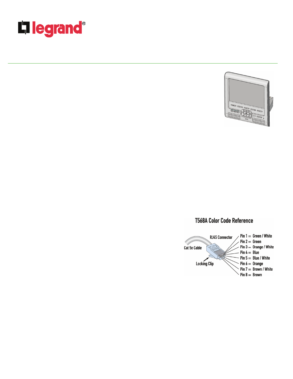
D. Terminate both ends of the Category 5 cables from the LCD Console, using RJ45 Plugs, according to the T568A wiring
standard (see Figure 2).
CAUTION: Be certain to properly label each cable, as reversal can cause equipment damage.
E. At the LCD Console location, use the included screws to fasten the display mounting bracket to the gang box.
IMPORTANT: Pull the cables coming through the gang box through the opening in the mounting bracket prior to fastening the
bracket to the box (see Figure 3).
F. Insert the RJ-45 plug from the Integration Module into the lower RJ-45 jack located on the rear of the LCD Console (see Figure 4) and
insert the RJ-45 plug from the lyriQ™ Distribution Module into the upper RJ-45 jack located on the rear of the LCD Console (see
Figure 4). The 16/2 power cable is attached to the two screw terminals of the 2-position connector on the rear of the LCD Console (see
Figure 4). The two 16/2 speaker cables are attached to the four speaker screw terminals of the 6-position connector on the rear of the
LCD Console (see Figure 4).
Figure 1
Figure 2