Legrand 364254-01 User Manual
Is-0073 rev. a
INSTRUCTION / INSTALLATION SHEET
Cable Modem Mounting Kit
IS-0073 Rev. A
301 Fulling Mill Road, Suite G
Middletown, PA 17057
Phone (800) 321-2343 / Fax (717) 702-2546
www.onqlegrand.com
©Copyright 2008 by On-Q/Legrand All Rights Reserved.
Page 1 of 1
1. INTRODUCTION
The On-Q Cable Modem Mounting Kit (P/N 364254-01) (see Figure 1) allows you to mount a wide
variety of cable modems directly into On-Q Enclosures.
2. DESCRIPTION
The On-Q Cable Modem Mounting Kit, when assembled, connects between the incoming cable service
and the video module for video service, telecom module wide area network inputs, telecom network
interface, or directly to the hub for 10BASE-T information service. It provides a 10BASE-T interface to
the delivered Information Services/Internet.
The kit includes the following items:
• One Panel with Cable Splitter
• One Velcro Strap
• One 15" F-F Cable
3. INSTALLATION
A. ASSEMBLY
1. Place Modem on mounting plate.
2. Secure modem using the velcro strap.
3. Connect F-F cable from output of cable splitter to the modem input "F" fitting.
B. MOUNTING IN ENCLOSURE
1. Align tabs on assembly with slots on rail of enclosure (see Figure 2).
2. Insert tabs by angling assembly away from the back of the enclosure and sliding forward.
3. Rotate the assembly and insert fasteners on assembly into corresponding holes on rail of enclosure. (Plunger
must be in the pulled out position for fastener to engage hole.)
4. Push plunger in to lock module in place. Pull on assembly to assure assembly is locked properly in place.
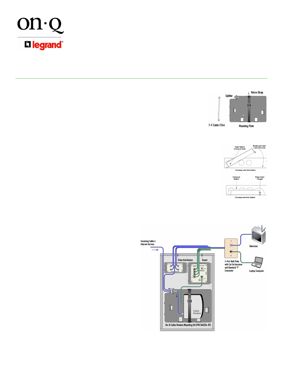
C. SERVICE CONNECTION
1. Identify incoming service cable and route to "Cable In"
fitting on splitter (see Figure 3). In routing cable, allow
slack for bundling cables to the side. Trim cable to
allow loose loop of cable to the connection.
2. Connect an RG6 Jumper Cable to "Cable Out" on
splitter. Route cable to "Cable In" input of video
distribution module.
3. Route a CAT 5 jumper cable to the "Wide Area
Network" or the "Data" input of a telecom module, a
network interface, or directly to a 10BASE-T hub.
4. Plug modem power supply into a 120 VAC source.
Figure 1
Figure 2
Figure 3