Legrand 364397-01 User Manual
Instruction/installation sheet network centers, Is-0141 rev. b
301 Fulling Mill Road, Suite G
Middletown, PA 17057
Phone (800) 321-2343 / Fax (717) 702-2546
www.onqlegrand.com
Page 1 of 2
INSTRUCTION/INSTALLATION SHEET
Network Centers
IS-0141 REV. B
©Copyright 2008 by On-Q/Legrand All Rights
Reserved
.
1. Introduction
The On-Q/Legrand Basic Network Center, Universal
Network Center and Advanced Network Center (see
Figure 1) provide a convenient method for installing
structured wiring in many residential applications. The
Universal and Advanced Network Centers provide
space for installation of On-Q Service Center modules
for other applications such as networking, home office,
audio and advanced video applications.
2. Description
The network centers combine both video and telecom
applications. The “video” portion has vertical access “F”
style fittings for connecting incoming and outgoing
cables.
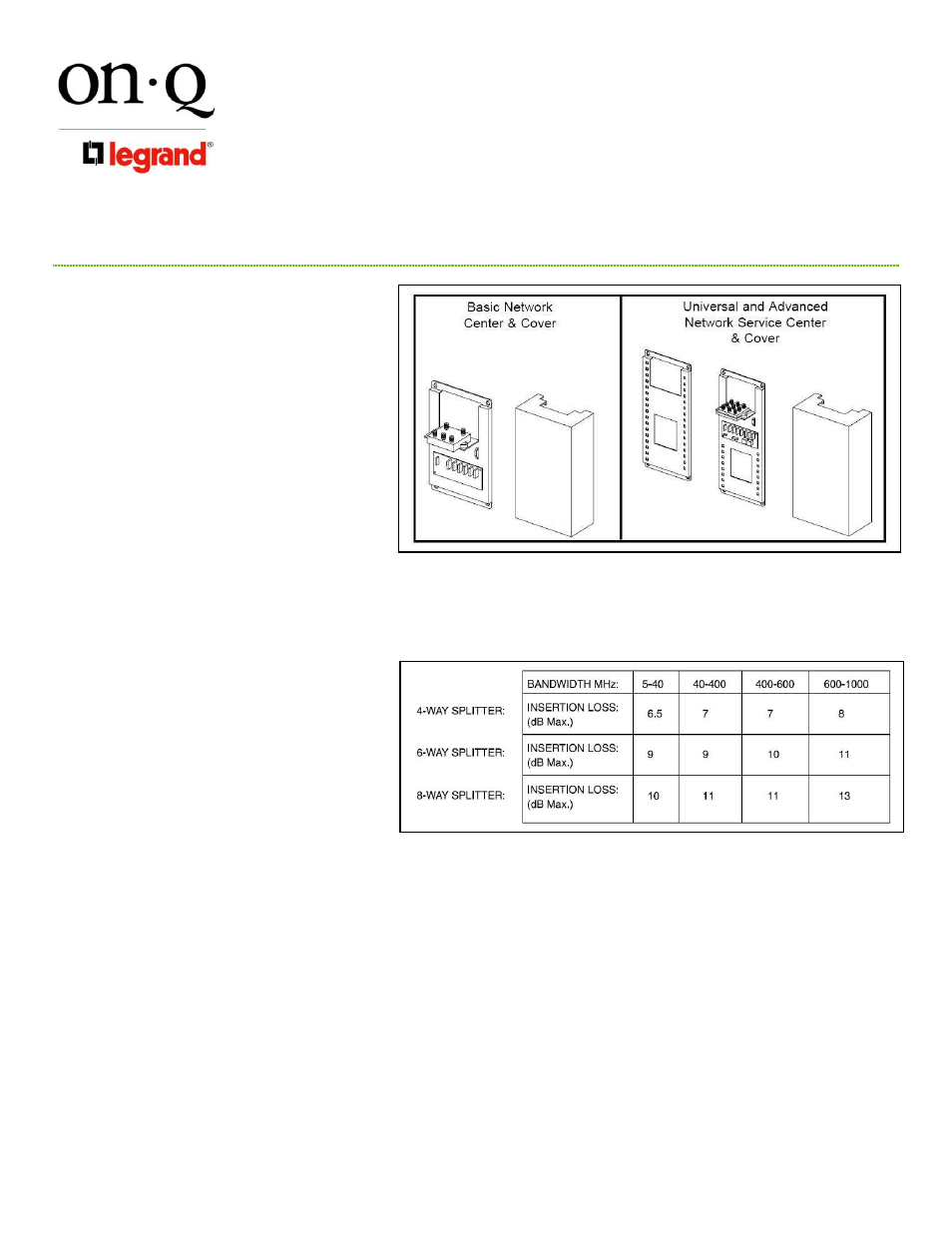
NOTE
– Video portion comes in several versions;
refer to Table 1 for insertion losses.
The “telecom” portion is also available in several
versions. All telecoms have an 8 position 110 punch-
down connector for incoming 4 line service and 110 (8)
position punch-down connectors for the extension
connections
Some modules also have an RJ-31X security interface
jack. The base plates and covers are constructed of
powder coated steel. The base plates incorporate a
grounding screw. The Basic Network Center is seven
(7) inches wide by twelve (12) inches long. The
Universal and Advanced Network Centers are seven (7)
inches wide by nineteen (19) inches long. The
Universal Network Service Center can be used in
combination with any On-Q half-width modules for
complete application flexibility.
3. Installation
A. Locating the Network Center
1) The network center should be located in a space which will remain between 0°C (32°F) and 50°C (122°F) and not be subject to humidity
levels which will allow condensation on the product. Areas of excess dust and dirt must also be avoided.
2)
The network center location must be such that it can be easily accessed to check and test connections.
3)
The network center should be located within two (2) feet of a standard 110 VAC outlet. The outlet should always be on and available for
use by upgrades to the network center.
B.
Cable Rough-In
1)
The cabling to and from the network center can either be surface run or behind the wall. To run the cable behind the wall, install a double
gang mud ring or junction box one (1) inch below the top of the network center.
2)
Follow NEC and local code requirement in running cables from the network center to the outlet locations.
3)
Route cables from the network center location to the outlet locations throughout the home.
NOTE: It is recommended to use Category 5e for telephone and data network wiring and quad shield RG6 coax for video
distribution.
NOTE: Avoid kinks and sharp bend radii in routing cable. At corners, feed cable round the corner. Cable should be routed to feed
easily. If cable is hard to pull, locate the area where it is bound and feed the cable through.
4)
Route service cables from the TelCo NID and service entry. It is recommended running two (2) Category 5e cables between the NID and
the network center and one (1) RG6 coax to the service entry.
5)
Mark all cables with application and location.
Figure 1
Table 1