Legrand 1267062-01 User Manual
Instruction / installation sheet telecom modules, Is-0058 rev. e
INSTRUCTION / INSTALLATION SHEET
Telecom Modules
IS-0058 Rev. E
301 Fulling Mill Road, Suite G
Middletown, PA 17057
Phone (800) 321-2343 / Fax (717) 702-2546
www.onqlegrand.com
©Copyright 2007 by On-Q/Legrand All Rights Reserved.
Page 1 of 3
1. Introduction
The On-Q/Legrand 1x6 Basic Telecom (P/N 1267062-01) and 6
Port Telecom Expansion Module (P/N 1267058-01) provide a
structured method for distributing telephone service through-out
a residence. The modules occupy three (3) vertical inches and
span half the width of an On-Q Service Center Enclosure.
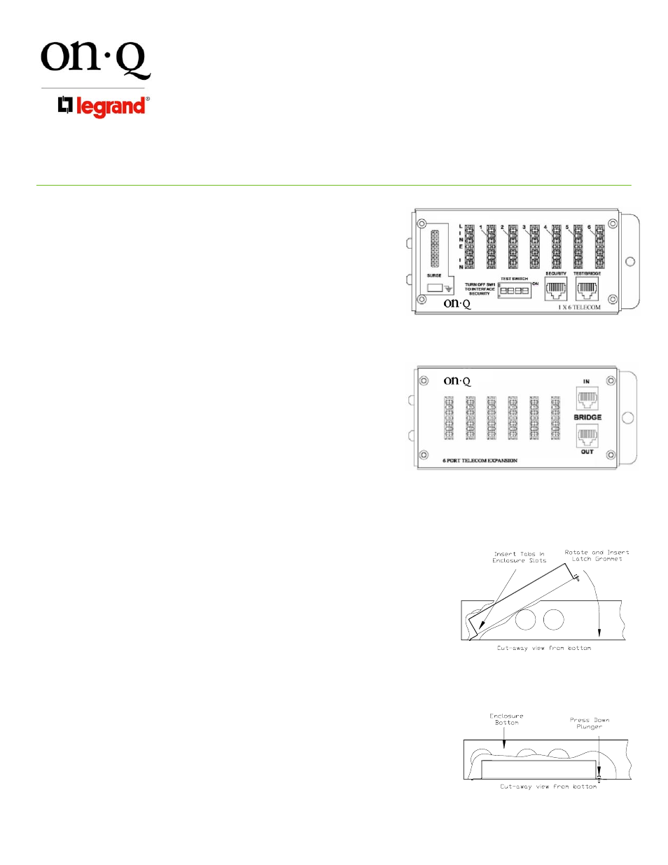
2. Description
The 1x6 Telecom Module (see Figure 1) has an eight position
110 punch-down connector for connecting the incoming four line
service, a two row 20 position posted connector and spade
terminal for optional surge protection (On-Q P/N 363487-01).
There is a vertical RJ45 jack for test for local handset attachment
and an additional vertical RJ45 jack for the RJ31X security
interface. Six 8 position 110 punch-down connectors for
connecting the outlets to the system are available. The module
also features a 4-position switch to allow separation of the
incoming lines from the outlets for testing purposes. The switch
is also used to activate the security option. The Telecom
Expansion Module (also see Figure 1) has two RJ45 vertical
telephone jacks for bridging connections and six 8 position, 110
punch-down connectors for outlet distribution.
3. Installation
A. Mounting in Enclosure - See Figure 2
1) Align tabs on the module with slots on rail of enclosure.
2) Insert tabs angling module away from the back of the enclosure.
3) Rotate the module and insert fasteners on module into
corresponding holes on rail of enclosure. (Plunger must be in a
pulled position for fastener to engage hole)
4) Push plunger in to lock module in place. Pull on module to
ensure module is locked properly in place.
B. Incoming Service Cable Installation (1x6 Telecom)
1) Identify incoming service cable and route to “Line In” 110 punch-
down block. In routing cable, allow slack or bundling to the side
and avoiding other cable terminations. Trim cable about 2
inches beyond connector.
2) Strip off approximately 4 inches of the outer jacket using On-Q
Strip Tool (P/N 363292-01 or equivalent).
3) Position pairs over color-coded slots on the connector (see
Figure 3).
NOTE: Do NOT untwist pairs.
Figure 2
Figure 1