Ab c, Installation and operating instructions, Black bare red – Louroe Electronics LE-071 User Manual
Page 3
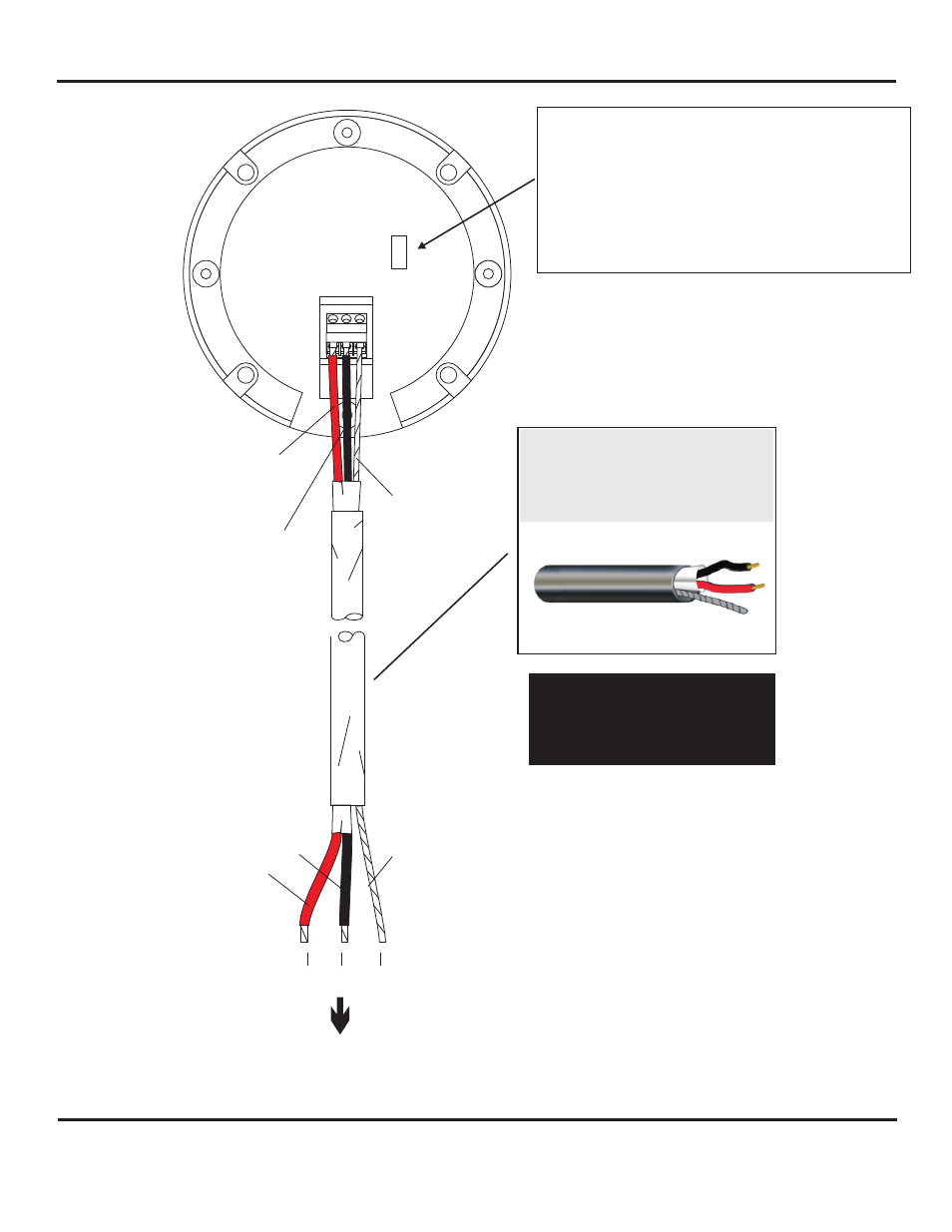
MICROPHONE SENSITIVITY SWITCH
The microphone pre-amp (PC board) contains a sensitivity
switch with two positions marked N and L, and is located on the
back side of the Model A near the terminal block:
N represents normal sensitivity
(0 dB @ 1,000
W)
L represents lower sensitivity
(-6 dB @ 1,000
W)
Microphone is always shipped in the N position. For less
microphone sensitivity, move slide switch to L position.
BARE
A B C
BACKSIDE OF
VERIFACT B
MICROPHONE
L
N
BLACK
RED
TO LOUROE BASE STATION
OR
AUDIO INTERFACE ADAPTERS
(IF-1, IF-2, IF-4, IF-8)
A = +12Vdc (RED)
B = Audio (BLACK)
C = Ground (BARE)
2 Conductor shielded cable, 22
gauge with a 24 gauge drain wire
NOTE:
Unshielded cable is not
satisfactory for audio systems
WIRING REQUIREMENTS
West Penn 452 or equivalent
A
B
C
BLACK
BARE
RED
INSTALLATION AND OPERATING INSTRUCTIONS
Page 3 of 4
LOUROE ELECTRONICS 6 9 5 5 VA L J E A N AVENUE, VAN NUYS, CA 91406
TEL (818) 994-6498
FAX
994-6458
website: www.louroe.com e-mail: [email protected]
(818)
®
B_mic_inst_11/14
®