Ab c, Installation and operating instructions – Louroe Electronics LE-510 User Manual
Page 3
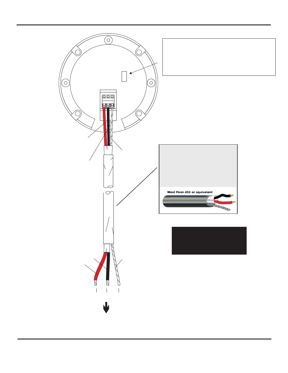
BARE
A B C
BACKSIDE OF
VERIFACT AGC
MICROPHONE
L
N
BLACK
RED
A
B
C
BLACK
BARE
RED
TO LOUROE™ BASE STATIONS OR AUDIO INTERFACES
OR
OTHER AUDIO RECEIVERS AND RECORDERS
A = +12Vdc (RED)
B = Audio (BLACK)
C = Ground (BARE)
2 Conductor shielded cable, 22
gauge with a 24 gauge drain
wire.
NOTE: Unshielded cable is not
satisfactory for audio
systems.
WIRING REQUIREMENTS
MICROPHONE GAIN ADJUSTMENT
Located inside the opening is an audio output gain
potentiometer. Microphone is always shipped with a 0dB output.
If it’s necessary to change the gain of the microphone, insert a
small screwdriver inside the opening and rotate the
potentiometer clockwise to increase or counterclockwise to
decrease.
INSTALLATION AND OPERATING INSTRUCTIONS
Page 3 of 4
LOUROE ELECTRONICS 6 9 5 5 VA L J E A N AVENUE, VAN NUYS, CA 91406
TEL (818) 994-6498
FAX
994-6458
website: www.louroe.com e-mail: [email protected]
(818)
®
®
Agc_mic-inst_12/14