Installation and operating instructions, Mounting tli to vrsc housing, This connections are the same for all tli models) – Louroe Electronics TLI Series User Manual
Page 4
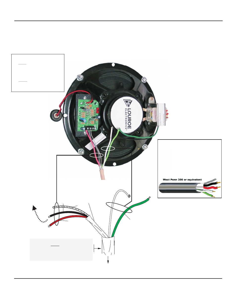
TO LOUROE AUDIO BASE STATION
OR OTHER AUDIO RECEIVING DEVICE
WIRING DIAGRAM FOR
MODEL TLI SERIES
SPEAKER/MICROPHONE
GREEN
(speaker
positive)
SAMPLE CABLE WEST PENN 356
+
2 Conductor shielded, 20 gauge with 22 gauge
drain (microphone connection)
+
2 Conductor unshielded, 18 gauge (speaker
connection)
West Penn 356 or equivalent
(all in the same jacket)
MOUNTING TLI TO VRSC HOUSING
Place TLI inside VRSC matching the 4 mounting screws
and secure with furnished nuts and washers.
No knockouts are provided on the VRSC. Bore a ¾”
opening at the desired side of VRSC for passing cable
through for connecting to TLI.
MICROPHONE
CONNECTIONS
RED
BLACK
BARE
INSTALLATION AND OPERATING INSTRUCTIONS
Page 4 of 8
LOUROE ELECTRONICS 6 9 5 5 VA L J E A N AVENUE, VAN NUYS, CA 91406
TEL (818) 994-6498
FAX
994-6458
website: www.louroe.com e-mail: [email protected]
(818)
®
1) Speaker Connection
White wire of West Penn 356
connects to Black wire
(COMMON) from TLI
Transformer using a wire nut.
2) Green wire of West Penn 356
connects to Green wire from TLI
Transformer using a wire nut.
(THIS CONNECTIONS ARE THE SAME FOR ALL TLI MODELS)
TLI_Series_inst_3/15
WIRING REQUIREMENTS
4 Conductor consisting of:
+ 2 Conductor shielded, 20 gauge
with 22 gauge drain (microphone
connection)
+ 2 Conductor unshielded, 18 gauge
(speaker connection)
All in the same jacket