Installation and operating instructions, Connections microphone to input side of if-1, Output side of if-1 to audio receiver – Louroe Electronics IF-1 User Manual
Page 2: Applying power to if-1, Audio out” control of potentiometer
CONNECTIONS
MICROPHONE TO INPUT SIDE OF IF-1
Wiring: 2 conductor Shielded 22 gauge with 24 gauge drain wire
West Penn 452 or equivalent
All Louroe microphones contain a terminal block or terminal strip
marked A, B, C.
A = 12 Vdc power (+)
B = Audio
C = Ground (-)
If using recommended wiring:
Connect red wire to terminal A of microphone
Connect black wire to terminal B of microphone
Connect bare wire to terminal C of microphone
OUTPUT SIDE OF IF-1 TO AUDIO RECEIVER
(DVR, IP Network Camera, etc.)
(A) If audio receiver is a DVR or VCR that has RCA input, use the single RCA cable to connect RCA output
of IF-1 to “Audio In” of DVR/VCR.
(B) If the audio receiver (DVR, Soundcard, etc.) has a 3.5mm stereo input, use the 3.5mm stereo cable
and connect to the 3.5mm stereo jack of the IF-1 before connecting to the “Audio In” or “Line In” of the
DVR or soundcard. NOTE:
DO NOT
connect to “Mic In” of soundcard.
© If audio receiver (IP Network camera, DVR, Video Server, etc.) has a 3.5mm mono input, connect the
RCA to 3.5mm mono cable to the RCA audio out of IF-1 to the “Audio In” or “Line In” of IP Network
camera, etc.
APPLYING POWER TO IF-1
A 12 Vdc AC Adapter is included with the IF-1. First connect small plug into 12 Vdc power jack on input side of IF-1.
Connect other end (power block) to standard 110V/120 Vac electronic outlet or power strip.
“AUDIO OUT” CONTROL OF POTENTIOMETER
Located on the IF-1 input side (next to 3-pin microphone terminal block) is a potentiometer for audio gain
adjustment. Occasionally, though rare, the microphone may overdrive (or underdrive) the audio signal into the IF-1.
Should this occur, use a small screw driver and move arrow clockwise to increase gain. Move counterclockwise to
lower gain. The potentiometer is positioned straight up at the factory.
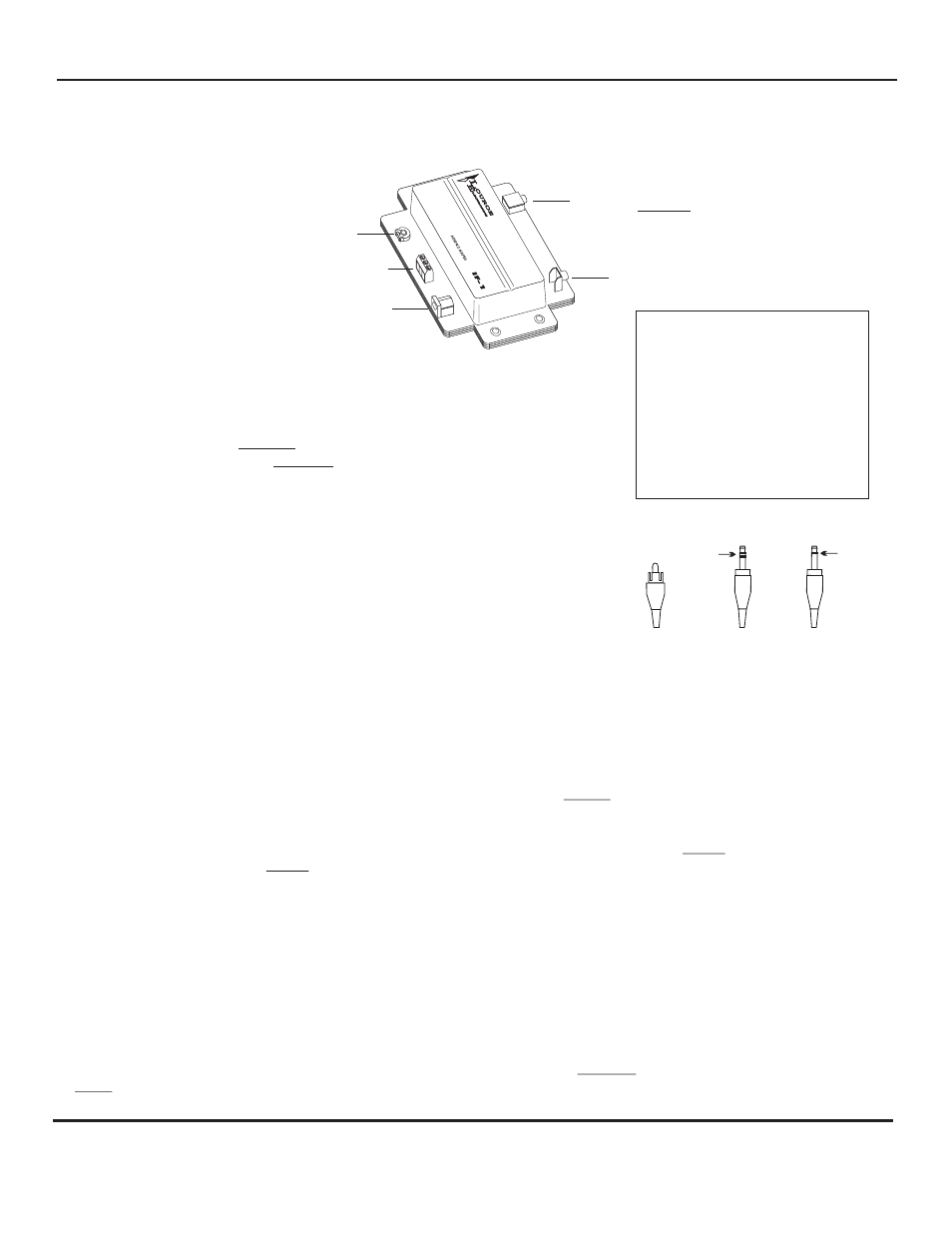
12 Vdc Power Jack
Model IF-1
Microphone Input Terminal Block
“Audio Out” Control
(Gain Adjustment)
RCA Audio Out Jack
3.5mm Stereo Audio Out Jack
Color Code for West
Penn 452
Red - 12Vdc
Black - Audio Output
Bare - Ground
If using cable from other
manufacturers, color code
may vary.
3.5mm
STEREO
3.5mm
MONO
Plug Identification
RCA PLUG
two bands
stereo
one band
mono
Types of plugs used with applications
in this instruction manual
INSTALLATION AND OPERATING INSTRUCTIONS
Page 2 of 8
LOUROE ELECTRONICS 6 9 5 5 VA L J E A N AVENUE, VAN NUYS, CA 91406
TEL (818) 994-6498
FAX
994-6458
website: www.louroe.com e-mail: [email protected]
(818)
®
IF_1_inst_5/15