Model dcs, Installation and operating instructions – Louroe Electronics DCS User Manual
Page 2
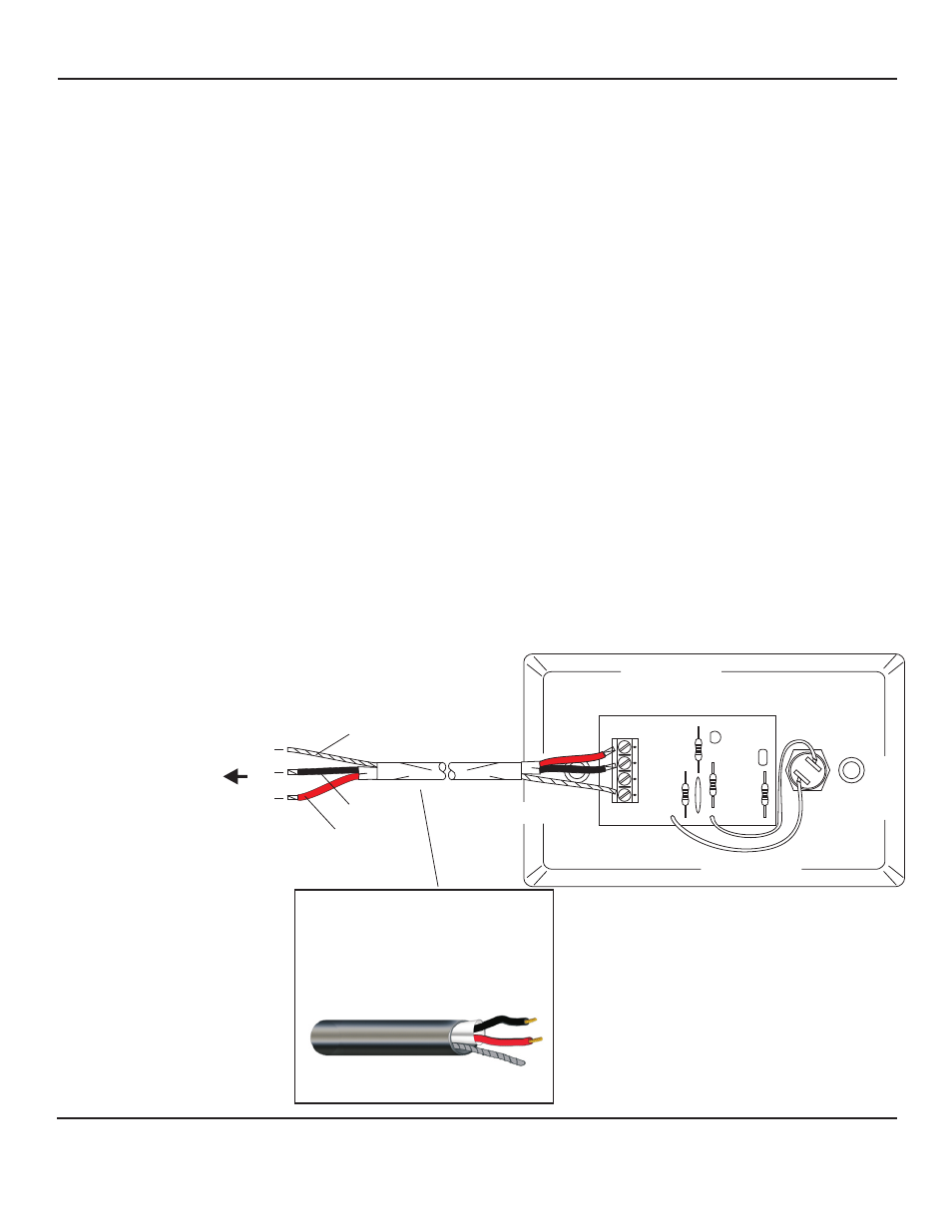
The PC Board of Model DCS contains a 4-pin terminal block marked 1, 2, 3, 4
1) Ground
2) Input from microphone (not used with this application)
3) Output of oscillator (3kHz)
4) 12Vdc power (positive)
NOTE: Pin #2 is used only when DCS is being connected to a Louroe Microphone
For connecting other end of West Penn 452 to the Louroe Base Station, please refer to the specific base station
instructions for proper connection.
CONNECTING MODEL DCS DIRECTLY TO LOUROE BASE STATION
If using recommended wiring connect as follows:
BARE wire connects to Pin #1 of DCS
BLACK wire connects to Pin #3 of DCS
RED wire connects to Pin #4 of DCS
Note: Pin #2 is not used
C
2
B
3
A
4
TO TERMINAL BLOCK OF
LOUROE DG SERIES BASE
STATION
REFER TO THE SPECIFIC BASE
STATION
INSTALLATION INSTRUCTIONS
FOR PROPER
CONNECTIONS
MODEL DCS
BLACK
BLACK
BARE
BARE
RED
RED
2 Conductor shielded cable, 22
gauge with a 24 gauge drain wire
NOTE:
Unshielded cable is not
satisfactory for audio systems
WIRING REQUIREMENTS
West Penn 452 or equivalent
1
INSTALLATION AND OPERATING INSTRUCTIONS
Page 2 of 4
LOUROE ELECTRONICS 6 9 5 5 VA L J E A N AVENUE, VAN NUYS, CA 91406
TEL (818) 994-6498
FAX
994-6458
website: www.louroe.com e-mail: [email protected]
(818)
®
dcs_inst_3/15