LSC Lighting Redback Wallmount Install Guide v1.1 User Manual
Wallmount dimmer installation guide, Lighting systems
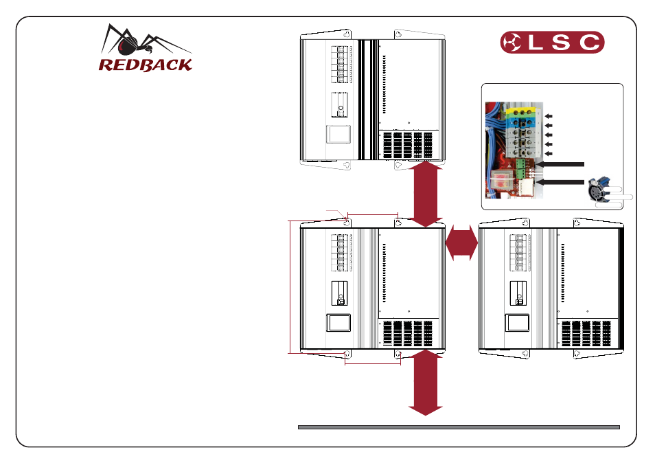
150.0 mm
392.0 mm 6CH
659.0 mm 12CH
1015.0 mm 24CH
166.0 mm
Mounting Holes
to suit M6 or
¼ inch Fasteners
4 Places
Min 100mm
Min
200mm
Min
300mm
FLOOR
Wallmount Dimmer Installation Guide
. (
)
-
. (
)
. (
)
-
(
)
,
,
,
Site/Job Name ..........................................................................................................................
Commissioning Date ................................................................................................................
Engineer/Technician ................................................................................................................
INSTALLATION CHECKLIST
Chassis correctly mounted with both top and bottom fasteners installed 4 places
Top and Bottom Ventilation holes are clear and free from debris
Rack Spacing and layout complies with installation guide diagram.
Wall structure is within guidelines for the mounting of electrical equipment
CONTROL INTERFACE CHECKLIST
DMX cable is RS485 compliant or shielded CAT5 cable
Remote wall plate cabling is 8 wire CAT5 type if applicable
DMX cable correctly terminated
if applicable
All wall plates correctly wired and installed
DMX termination switch is set correctly within Rack
REDBACK RACK WIRING CHECKLIST
Mains input wiring is correctly terminated
All mounting/termination screws are tight
Neutral per load, no floating neutrals or Earths in the system
Check Phase to Earth impedance
Check Phase to Phase impedance
Check Phase Neutral impedance =1.5K +/- 200 ohm
POWER UP CHECKLIST
Measure Neutral to Earth Voltage
15V
Measure Neutral to Line L1 L2 and L3 voltage
Measure Phase to Phase L1-L2 L2-L3 L3-L1 voltages
Test Output circuits for any fault condition
£
£
£
£
¨
¨
¨
¨
¨
¨
¨
¨
¨
¨
¨
¨
¨
¨
¨
›100K ohm
›=2.8K ohm
N-E =.........................V
L1-N =.........................V
L2-N =.........................V
L3-N =.........................V
L1-L2 =.........................V
L2-L3 =.........................V
L3-L1 =.........................V
All cover plates in place and conduit air gaps sealed
‹=
¨
These checks should be performed before power is applied to the rack.
WARNING! - DO NOT MEGGER TEST ANY WIRED CONNECTIONS TO THE RACK
These checks should be performed before power is applied to the rack.
The following checks are performed with power applied to the rack.
Redwall install guide V1.1 Document# RBW-T02U-A1
LIGHTING SYSTEMS
INPUT WIRING TERMINATION
L1
L2
L3
N
E
www.lsclighting.com
Pin1 COM
Pin2 DMX MINUS
Pin3 DMX PLUS
RJ45 REDPLATE (UNDERSIDE)
RJ45 REDPLATE (UNDERSIDE)
Pin3 DMX PLUS
Pin1 COM
Pin2 DMX MINUS