0 the cutting process, Caution – Mathey Dearman 6SA Saddle Machine User Manual
Page 9
9
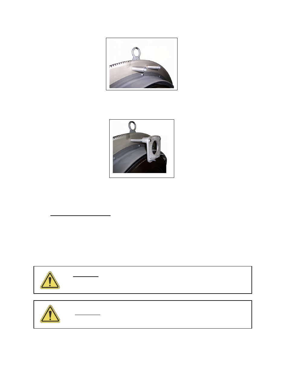
5.1.1
Thread the Extension Plate Spacers (Figure 5 item 21) on to the Threaded Studs (Figure 5 item 19)
located on the Ring Gear (Figure 5 item 3).
Picture 5 – Installation of Extension Plate Spacer
5.1.2
Place 5/16”- 18 X 2” Long Hex Head Cap Screw (Figure 5 item 22) through Extension Plate (Figure 5
item 20) and thread into Extension Plate Spacer (Figure 5 item 21).
Picture 6 – Extension Plate Attached to Extension Plate Spacer
5.1.3 Install Torch Arm over the threaded Studs located on the Extension Plate (Figure 5 item 20).
5.1.4 To install the Torch Carrier Assembly (Figure 3 item B) and Machine Torch follow instructions 5.03
through 5.08 .
6.0 The Cutting Process
6.1
Rotate Torch one full turn around the pipe to be sure torch tip will maintain the same distance around the pipe.
Note: If the torch tip contacts the pipe at any point during its rotation either the incorrect spacer bolts were
selected or the pipe is oversize or out of round. If the distance of the torch tip is greater at the 6:00 o’clock
either the incorrect spacer bolts were selected or the pipe is undersize.
6.2
Connect the gas hose from the fuel regulator to the left hand thread port 10” long Oxy/fuel Machine Torch per
the manufacturer’s instructions.
6.3
Connect the oxygen hose from the oxygen regulator to the right hand thread port 10” long Oxy/fuel Machine
Torch per the manufacturer’s instructions.
Caution:
T
he hose must not be drawn through the molten slag produced by the
cutting process
Caution:
T
he oxygen and fuel hoses must be connected to the right port on the
machine torch. Failure to do so may result in serious injury.