Locate wall stud(s), Mark rear wall – Maytag MMV1163DW Installation User Manual
Page 6
6
Locate Wall Stud(s)
NOTE: If no wall studs exist within the cabinet opening, do not
install the microwave oven.
See illustrations in “Possible Wall Stud Configurations.”
1. Using a stud finder, locate the edges of the wall stud(s) within
the opening.
2. Mark the center of each stud, and draw a plumb line down
each stud center. See illustrations in “Possible Wall Stud
Configurations.”
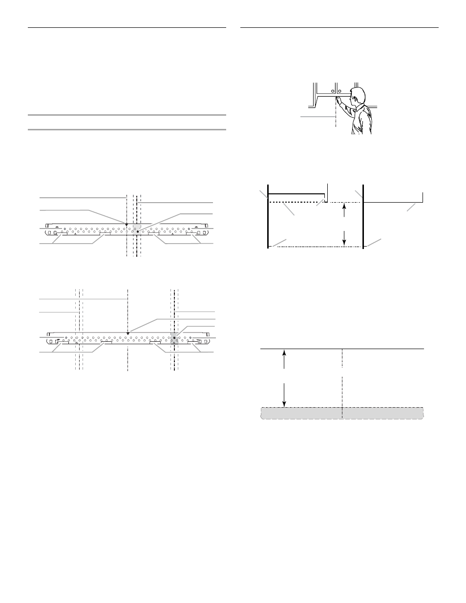
Possible Wall Stud Configurations
These depictions show examples of preferred installation
configurations with the mounting plate.
NOTE: If wall stud is within 6" (15.2 cm) of the vertical centerline
(see “Mark Rear Wall” section), only recirculation or roof venting
installation can be done.
Figure 1 - One Wall Stud
Figure 2 - Two Wall Studs
NOTE: Holes are for installation with 1 lag screw into the wall stud
and 2 toggle bolts through the drywall.
Mark Rear Wall
The microwave oven must be installed on a wall stud using a lag
screw, plus 2 toggle bolts through the drywall.
1. Using measuring tape, find and clearly mark the vertical
centerline of the opening.
A. Centerline
2. Mark the centerline 14
¹⁄₂" (36.8 cm) down from bottom edge of
the upper cabinet (or flush line, if upper cabinet has a hanging
front edge – see illustration).
3. Using a straightedge, draw a level, horizontal line through the
mark made in Step 2. This represents the top edge of the
mounting plate.
4. Remove the mounting plate and check the markings:
The top edge line must be 14
¹⁄₂" (36.8 cm) from the bottom of
the upper cabinet, and must be level.
5. With the support tabs facing forward (see illustrations in
“Locate Wall Stud(s)” section), align the mounting plate center
marker to the centerline on the wall, making sure its top edge
is aligned with the horizontal line drawn in Step 3. Make sure
the mounting plate is level.
6. Through the mounting plate, mark a hole at each end of the
mounting plate. These are the mounting holes.
NOTE: If both mounting holes are over wall studs, mark another
hole that is not over the wall stud near the left end of the mounting
plate. This is the new mounting hole for the left side.
A. Cabinet opening vertical centerline
B. Holes for toggle bolts
C. Wall stud centerlines
D. Hole for lag screw
E. Support tabs
F. Mounting plate center marker
A
B
B
C
D
E
E
F
D
A
C
C
F
E
E
B
B
A. Rear wall
B. Hanging front edge of upper cabinet
C. Flush line
D. Mark for top edge of mounting plate
E. Bottom of smooth bottom upper cabinet
A
A
A
C
D
D
E
B
14
¹⁄₂
"
(36.8 cm)
Upper cabinet bottom
Top edge of mounting plate
14
¹⁄₂"
(36.8 cm)
Centerline