Measurement Computing CIO-DAS16/330 User Manual
Page 28
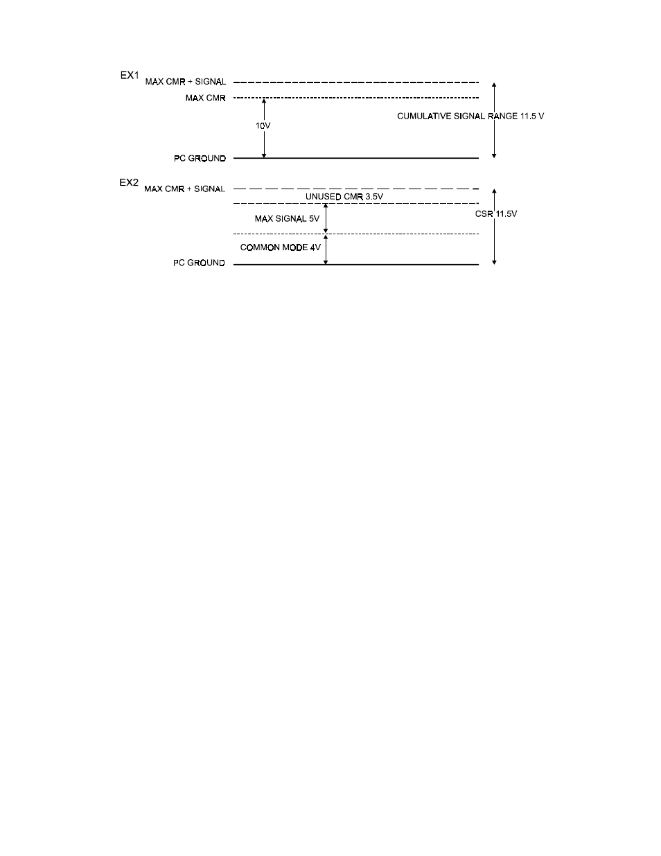
This specification is illustrated graphically in Figure 6-4 and is referred to as Cumulative Signal Range (CSR).
Figure 6-4. Cumulative Signal Range
Most manufactures of A/D boards specify the CMR directly from the component data sheet, ignoring the effect of the
board level system on that specification. A data sheet of that type might claim 10 volts of CMR. Although this is a
factual specification and the designer of the board (or other EE) would be able to translate that into a systems
specification, most A/D board owners are confused or mislead by such specs.
COMMON MISUNDERSTANDINGS
The CMR specification of a differential input is often confused with an isolation specification, which it is not. It makes
sense. doesn't it, that 10 volts of CMR is the same as 10 volts of isolation? No. The graph above shows why.
Also, failure to specify the common mode plus signal system specification leads people to believe that a DC offset equal
to the component CMR can be rejected regardless of the input signal voltage. It cannot as the graph above illustrates.
When is a differential input useful? The best answer is whenever electromagnetic interference (EMI) or radio frequency
interference (RFI) may be present in the path of the signal wires. EMI and RFI can induce voltages on both signal wires
and the effect on single ended inputs is generally a voltage fluctuation between signal high and signal ground.
A differential input is not affected in that way. When the signal high and signal low of a differential input have EMI or
RFI voltage induced on them, that common mode voltage is rejected, subject to the system constraint that common mode
plus signal not exceed the A/D board's CSR specification.
GROUND LOOPS
Ground loops are circuits (E=I*R) created when the signal ground and the PC ground are not the same. Ground loop
inducing voltage differential may be a few volts of hundreds of volts. They may be constant or transient (spikes). A
differential input will prevent a ground loop as long as the CSR specifications is not exceeded.
If ground differences greater than the CMR are encountered, isolation is required.
WHY USE SINGLE ENDED?
The reason is connector space. Single ended inputs require one analog high input per channel and one LLGND shared by
all inputs. Differential inputs require signal high and signal low inputs for each channel and one common shared
LLGND.
Single ended inputs save connector space, parts cost and in all cases where there is no common mode or EMI/RFI they
work just as well as differential inputs and are less complex to wire up.
24