Installing the cio-diso48, Connecting the board for i/o operations, Connectors, cables – i/o connectors – Measurement Computing CIO-DISO48 User Manual
Page 11: Pin out – i/o connectors
CIO-DISO48 User's Guide
Installing the CIO-DISO48
10
Installing the CIO-DISO48
After you configure the board's switches and jumper, you can install the CIO-DISO48 into your computer. To
install your board, follow the steps below.
Install the MCC DAQ software before you install your board
The driver needed to run your board is installed with the MCC DAQ software. Therefore, you need to install the
MCC DAQ software before you install your board. Refer to the Quick Start Guide for instructions on installing
the software.
1. Turn your computer off, open it up, and insert your board into an available ISA slot.
2. Close your computer and turn it on.
3. To test your installation and configure your board, run the InstaCal utility you installed in the previous
section. Refer to the Quick Start Guide that came with your boar
for information on how to initially set up and load InstaCal.
Connecting the board for I/O operations
Connectors, cables
– I/O connectors
The table below lists the board connectors, applicable cables and compatible accessory boards.
Board connectors, cables, accessory equipment
I/O connector type
P1 and P2: 50-pin header connectors
Compatible cable
C50FF-x, where x = length in feet
Compatible accessory products with the C50FF-x cable
CIO-MINI50 (two required to monitor more than 24 channels)
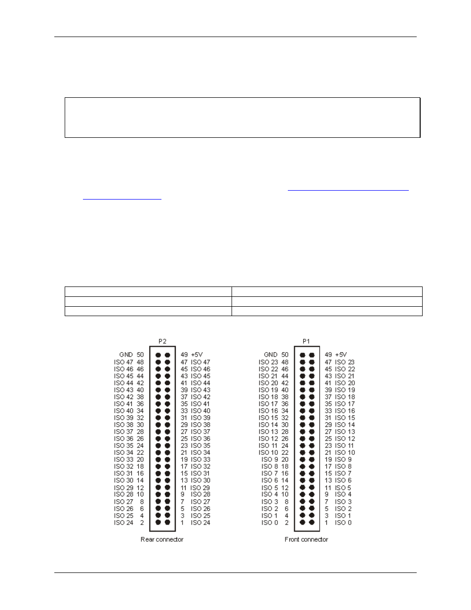
Pin out
– I/O connectors
Figure 4. Front and rear connector pin out