Measurement Computing DADP-5037 User Manual
Dadp-5037 connection guide
P3
PORT A_0 1
3
5
7
9
11
13
15
7
19
21
23
PASS_1 25
9
31
33
35
37
39
41
43
45
47
49
PORT A_2
PORT A_4
PORT A_6
PORT B_0
PORT B_ 2
PORT B_ 4
PORT B_ 6
PORT C_ 0 1
PORT C_ 2
PORT C_ 4
PORT C_ 6
PASS_3 27
PASS_5 2
PASS_7
PASS_9
PASS_11
PASS_13
PASS_15
PASS_17
PASS_19
PASS_21
PASS_23
PASS_25
2 PORT A_1
4
6
8
10
12
14
16
18
20
22
24
26 PASS_2
28
30
32
34
36
38
40
42
44
46
48
50
PORT A_3
PORT A_5
PORT A_7
PORT B_1
PORT B_3
PORT B_5
PORT B_7
PORT C_1
PORT C_3
PORT C_5
PORT C_7
PASS_4
PASS_6
PASS_8
PASS_10
PASS_12
PASS_14
PASS_16
PASS_18
PASS_20
PASS_22
PASS_24
GND
P1
PORT A_0 1
3
5
7
9
11
13
15
7
19
21
23
PASS_1 25
9
31
33
35
37
39
41
43
45
47
49
PORT A_2
PORT A_4
PORT A_6
PORT B_0
PORT B_ 2
PORT B_ 4
PORT B_ 6
PORT C_ 0 1
PORT C_ 2
PORT C_ 4
PORT C_ 6
PASS_3 27
PASS_5 2
PASS_7
PASS_9
PASS_11
PASS_13
PASS_15
PASS_17
PASS_19
PASS_21
PASS_23
PASS_25
2 PORT A_1
4
6
8
10
12
14
16
18
20
22
24
26 PASS_2
28
30
32
34
36
38
40
42
44
46
48
50
PORT A_3
PORT A_5
PORT A_7
PORT B_1
PORT B_3
PORT B_5
PORT B_7
PORT C_1
PORT C_3
PORT C_5
PORT C_7
PASS_4
PASS_6
PASS_8
PASS_10
PASS_12
PASS_14
PASS_16
PASS_18
PASS_20
PASS_22
PASS_24
GND
PORT A_0 37
36
35
34
33
32
31
30
29
28
27
26
25
24
23
22
21
20
PORT A_1
PORT A_2
PORT A_3
PORT A_4
PORT A_5
PORT A_6
PORT A_7
PORT C_0
PORT C_1
PORT C_2
PORT C_3
PORT C_4
PORT C_5
PORT C_6
PORT C_7
GND
19 n/c
18 n/c
17 n/c
16
15
14
13
12
11
10
9
8
7
6
5
4
3
2
1
n/c
n/c
n/c
n/c
n/c
n/c
PORT B_0
PORT B_1
PORT B_2
PORT B_3
PORT B_4
PORT B_5
PORT B_6
PORT B_7
n/c
n/c
P2
+5V Reg.
1 2 3
IN
OUT
GND
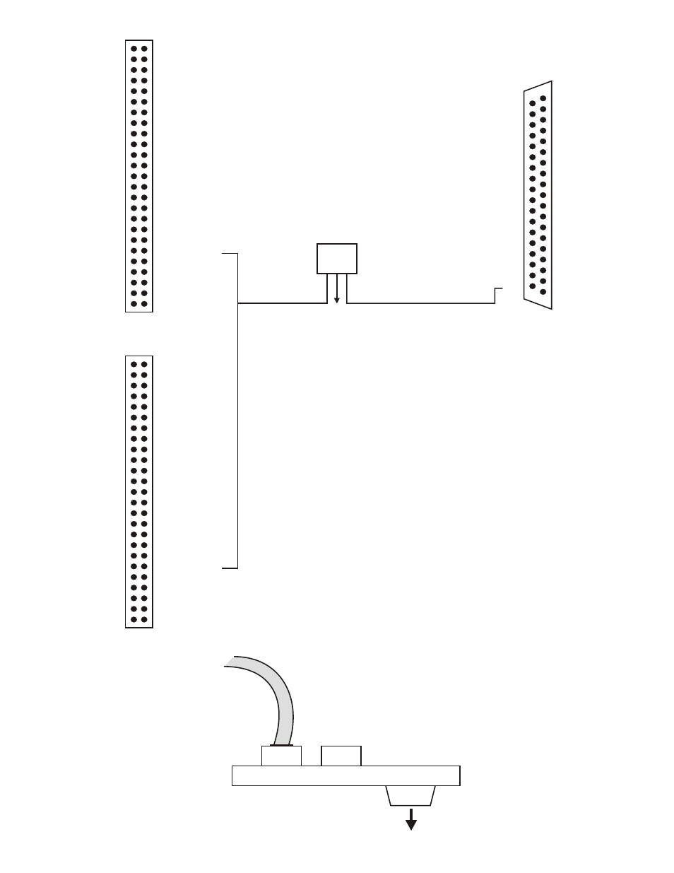
The DADP-5037 adapter board allows PCI analog I/O boards to interface and control
signal conditioning and accessory boards. The DADP-5037 connects the digital I/O bits
from the PCI board’s 100-pin I/O connector to those external accessory and signal
conditioning boards
using 37D I/O-type connectors.
# Connector P1 and P3 are wired 1:1, which allows either connector to be used as the
main interface between the PCI board and the DADP-5037. The unused 50-pin
connector can be used for applications that require you to monitor the I/O signals of
the connector in use. Consult your DAS manual’s I/O connector pin assignment
section to verify which signals are available at the connector being monitored.
Notes:
# Position U1 is reserved for the installation of a voltage regulator
(MCC p/n TN-MC78M05CT). The voltage regulator should only be used with
accessory boards that are powered
through the 37D connector, such as the
SSR-RACK08 board.
DADP-5037 Connection Guide
To accessory board’s
37D I/O connector
P3
P1
P2
C100FF-X
51-100 Cable
DADP-5037
U1
DADP-5037 Connector Map.cdr
© 2003 Measurement Computing Corporation
Document Revision 2