Screw terminal wiring, Screw terminal pins 1-15, Screw terminal pins 16-30 – Measurement Computing miniLAB-1008 User Manual
Page 16: Screw terminal wiring -4
miniLAB 1008 User's Guide
Functional
Details
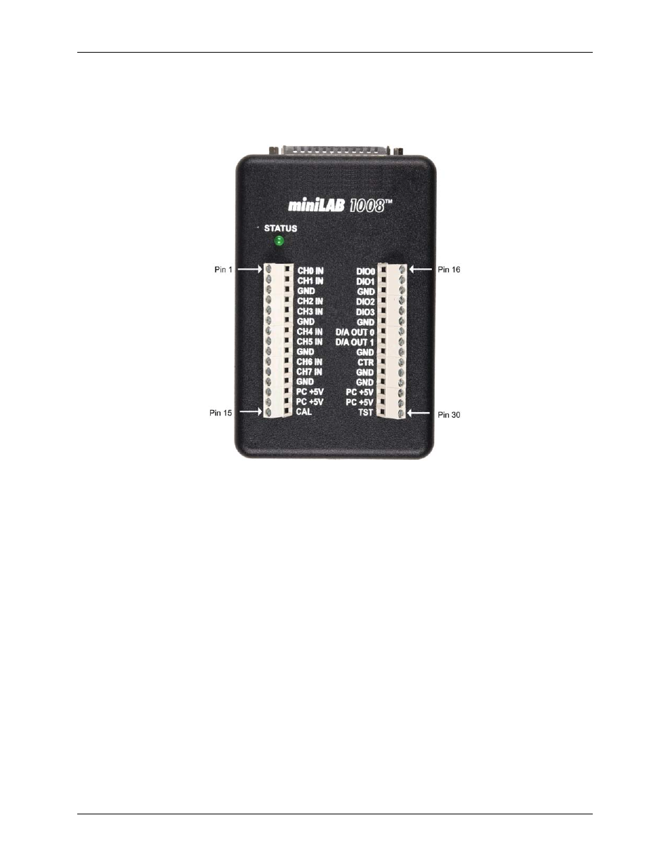
Screw terminal wiring
The miniLAB 1008 has two rows of screw terminals. Each row has 15 connections. Pin numbers are identified
in
. The pins are labeled for eight-channel single-ended mode operations.
Figure 3-3. miniLAB 1008 screw terminals
Screw terminal pins 1-15
The screw terminals on the left edge of the miniLAB 1008 (pins 1 to 15) provide the following connections:
!
Eight analog input connections (
CH0 IN
to
CH7 IN
)
!
Four GND connections (
GND
)
!
One calibration terminal (
CAL
)
!
Two power connectors (
PC +5 V
)
Screw terminal pins 16-30
The screw terminals on the right edge of the miniLAB 1008 (pins 16 to 30) provide the following connections:
!
Four digital I/O connections (
DIO0
to
DIO3
)
!
Two analog output connections (
D/A OUT 0
to
D/A OUT 1
)
!
One external event counter connection (
CTR
)
!
One testing and calibration terminal (
TST
)
!
Five ground connections (
GND
)
!
Two power connectors (
PC +5 V
)
3-4