Field wiring and signal termination, Field wiring and, Signal termination – Measurement Computing PCI-PDISO16 User Manual
Page 15
PCI-PDISO16 User's Guide
Installing the PCI-PDISO16
15
20
1
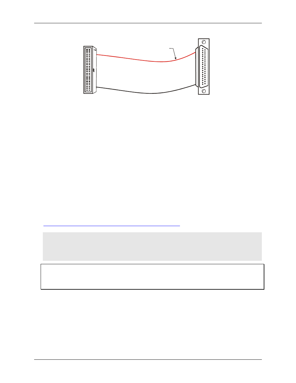
37
19
The red stripe
identifies pin # 1
37-pin Female
Dsub connector
50-pin Female
IDC Connector
1
2
49
50
Figure 5. C50-37F-x adaptor cable
Field wiring and signal termination
You can use the following screw terminal boards to terminate field signals and route them into the PCI-
PDISO16 using the C50FF-x cable:
CIO-MINI50 – 50-pin screw terminal board.
CIO-TERM100 – 100-pin screw terminal board.
SCB-50 – 50 conductor, shielded signal connection/screw terminal box provides two independent 50-pin
connections.
You can use the following screw terminal boards to terminate field signals and route them into the PCI-
PDISO16 using the C50-37F-x adaptor cable:
CIO-MINI37 – 37-pin screw terminal board.
CIO-TERMINAL – 37-pin screw terminal board with on-board prototype area.
SCB-37 – 37 conductor, shielded signal connection/screw terminal box providing two independent 37-pin
connections.
Details on these products are available on our web site at
Caution! Do not use the CIO-MINI50 screw terminal board if your field voltages are greater than 24 volts.
The CIO-MINI50 does not have shields to protect users from accidental contact with hazardous
high voltage signals. Construct a safe, fully insulated cable to carry your signals directly from your
equipment to the PCI-PDISO16 connector. If you use a screw terminal board, ensure that it is fully
enclosed in an insulated, protected box.
Additional signal conditioning is not required
The PCI-PDISO16 is designed with signal conditioning installed. Most accessory boards are intended to
provide signal conditioning or easy-to-access signal termination. In general, the PCI-PDISO16 does not require
additional signal conditioning.