Pins 21 to 28, And pins 32 to 39, Figure 3-4 – Measurement Computing USB-1024LS User Manual
Page 13: Usb-1024ls user's guide functional details, Port c0, Port c7, Port a0, Port a7, Port b0, Port b7
USB-1024LS User's Guide
Functional Details
20
CT
R
19
GN
D
18
n/
c
17
GN
D
16
n/
c
15
GN
D
14
n/
c
13
n/
c
12
GN
D
11
n/
c
10
n/
c
9G
N
D
8P
o
rt
C
7
7P
o
rt
C
6
6P
o
rt
C
5
5P
o
rt
C
4
4P
o
rt
C
3
3P
o
rt
C
2
2P
o
rt
C
1
1P
o
rt
C
0
GN
D
40
GN
D
31
PC
+
5
V
30
GN
D
29
Po
rt
A
7
28
Po
rt
B7
39
Po
rt
B6
38
Po
rt
B5
37
Po
rt
B4
36
Po
rt
B3
35
Po
rt
B2
34
Po
rt
B1
33
Po
rt
B0
32
Po
rt
A
6
27
Po
rt
A
5
26
Po
rt
A
4
25
Po
rt
A
3
24
Po
rt
A
2
23
Po
rt
A
1
22
Po
rt
A
0
21
Digital I/O terminals (Port A0 to A7, Port B0 to B7, Port C0 to C7)
Connect up to 24 digital I/O lines to the screw terminal containing pins 1 to 8 (
Port C0
to
Port C7
), pins 21 to
28 (
Port A0
to
Port A7
), and pins 32 to 39, (
Port B0
to
Port B7
). Refer to the pinout diagram on page 2 for the
location of these pins. You can configure each digital port for either input or output.
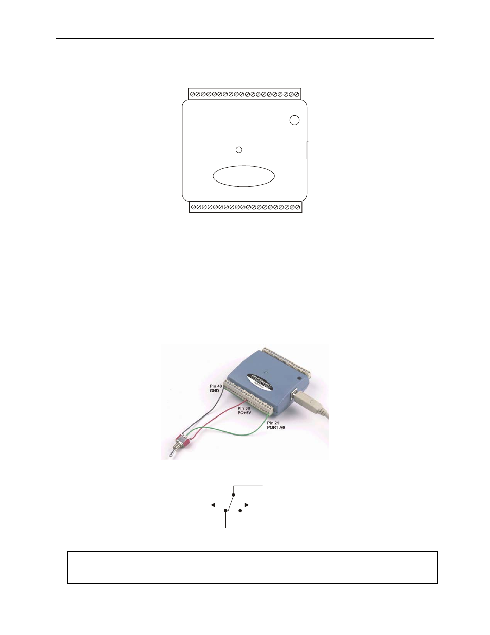
When configured for input, you can use the USB-1024LS digital I/O terminals to detect the state of any TTL
level input. Refer to the switch shown in Fi
and the schematic shown in
. If the switch is set
to the +5 V input, Port A0 reads TRUE (1). If you move the switch to GND, Port A0 reads FALSE.
Figure 3-3. Digital connection of Port A0 detecting the state of a switch
Figure 3-4. Schematic showing switch detection by digital channel Port A0
+5V
+GND
Port A0
For more information on digital signal connections
For more information on digital signal connections and digital I/O techniques, refer to the Guide to Signal
Connections (available on our web site at
3-3