Analog output, External clock i/o – Measurement Computing USB-1208HS-4AO User Manual
Page 12
USB-1208HS-4AO User's Guide
Functional Details
12
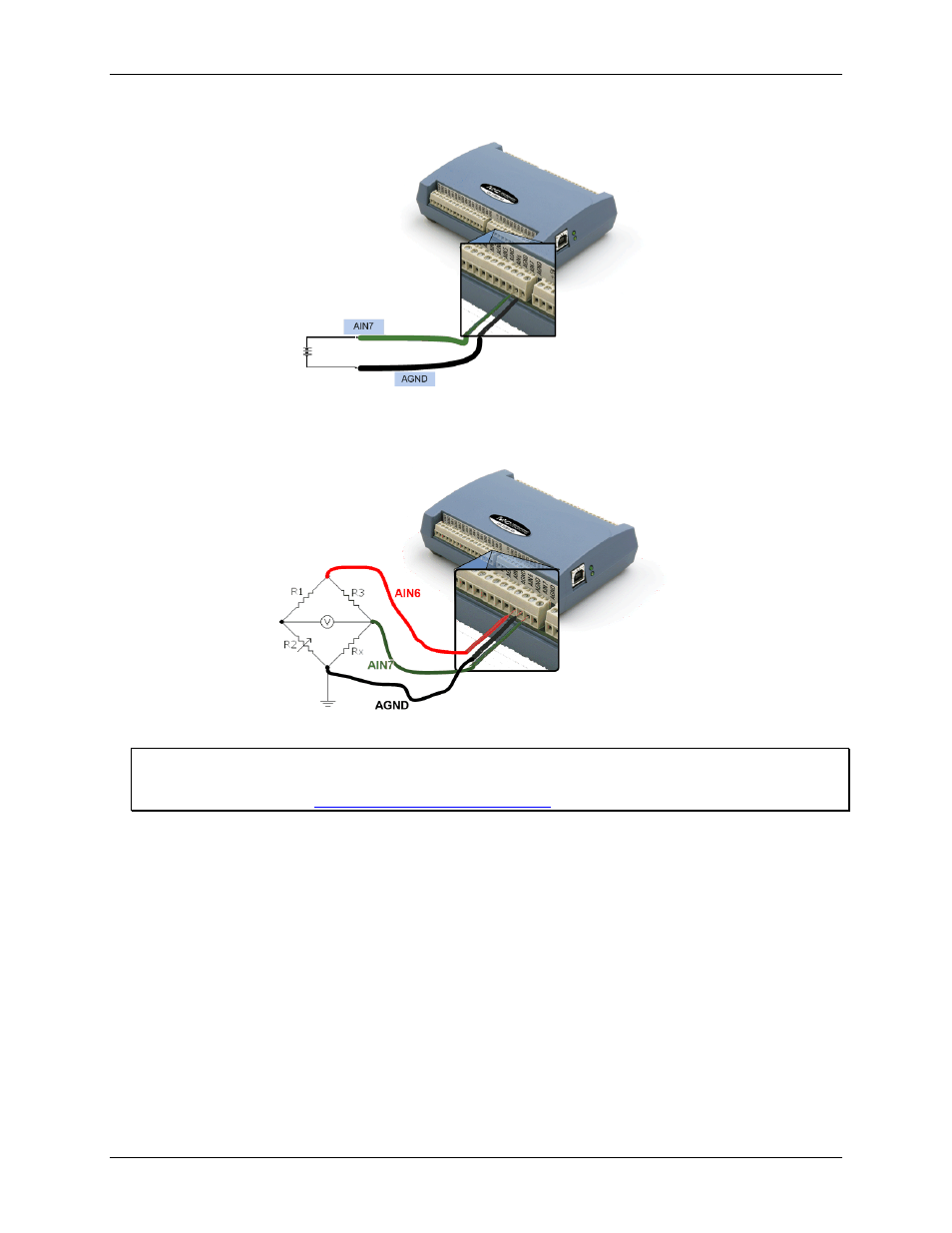
Figure 5 depicts a voltage source connected to a USB-1208HS-4AO configured for SE mode.
Figure 5. Single-ended measurement connection
Figure 6 depicts a Wheatstone bridge signal source connected to a USB-1208HS-4AO configured for DIFF
mode.
Figure 6. Differential measurement connection
For more information on analog signal connections
For more information on single-ended inputs, refer to the Guide to DAQ Signal Connections (this document is
available on our web site at
Analog output
You can connect up to four analog output connections to screw terminals
AOUT0
to
AOUT3
. Refer to Figure 4
and Figure 3 on page 10 for the location of these pins.
Each channel can be software-paced at rates up to 5,000 updates per second (system-dependent), or hardware-
paced at rates up to 1 MS/s.
Each analog output on the USB-1208HS-4AO has a fixed ±10 V output range. The outputs default to 0 V at
power up.
External clock I/O
The USB-1208HS-4AO device provides one external clock input (
AICKI
) and one external clock output
(
AICKO
) for analog inputs, and one external clock input (
AOCKI
) and one external clock output (
AOCKO
) for
analog outputs.