Power terminal (+5v ext), Counter terminal (ctr) – Measurement Computing USB-1608HS User Manual
Page 18
USB-1608HS User's Guide
Functional Details
18
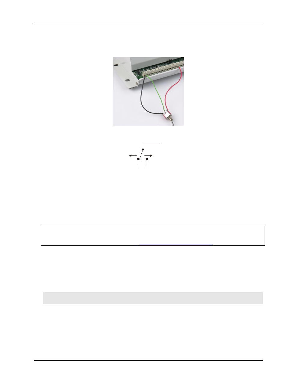
You can use the USB-1608HS digital I/O terminals to detect the state of any TTL-level input. Refer to the
switch circuit shown in Figure 8 and the schematic shown in Figure 9. If you set the switch to the +5V EXT
input, DI0 reads TRUE (1). If you move the switch to GND, DI0 reads FALSE (0).
Figure 8. Digital connection DI0 detecting the state of a switch
Figure 9. Schematic showing switch detection by digital channel DI0
Each digital input and digital output pin has an associated LED status indicator. A high at the pin lights the
LED.
You can disable the LEDs with jumpers. There is a jumper for the input LEDs, and a jumper for the output
LEDs.
For more information on digital signal connections
For general information regarding digital signal connections and digital I/O techniques, refer to the Guide to
Signal Connections (available on our web sit
Power terminal (+5V EXT)
You can use the
+5V EXT
connection to supply power to external devices or circuitry. This terminal can output
up to 10 mA.
Refer to the pinout diagram on page 14 for the location of this pin.
Caution! The
+5V EXT
terminal is an output. Do not connect to an external power supply or you may
damage the USB-1608HS and possibly the computer.
Counter terminal (CTR)
The
CTR
terminal is a TTL-level input to a 32-bit event counter. Refer to the pinout diagram on page 14 for the
location of this pin. The internal counter increments when the TTL level transitions from low to high. The
counter can count frequencies of up to 1 MHz.
GND
DI0
+5V EXT
+5V EXT
GND
DI0