Measurement Computing USB-2527 User Manual
Page 41
USB-2527 User's Guide
Functional Details
41
Note that the number of Z-reference crossings can be tabulated. If the encoder was turning in only one direction,
then the Z-reference crossings equal the number of complete revolutions. This means that the data streaming to
the PC is relative position, period = 1/velocity, and revolutions.
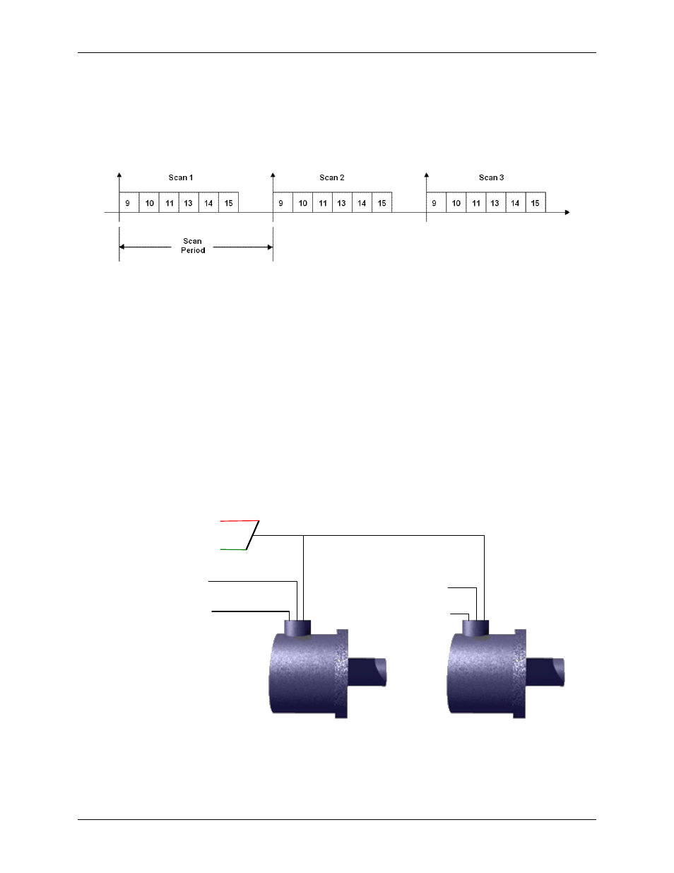
A typical acquisition might take six readings off of the USB-2527 as illustrated below. The user determines the
scan rate and the number of scans to take.
Figure 22. USB-2527 acquisition of six readings per scan
Digital channels do not take up analog channel scan time.
In general, the output of each channel’s counter is latched at the beginning of each scan period (called the start-
of-scan.) Every time the USB-2527 receives a start-of-scan signal, the counter values are latched and are
available to the USB-2527.
The USB-2527 clears all counter channels at the beginning of the acquisition. This means that the values
returned during scan period 1 are always zero. The values returned during scan period 2 reflect what happened
during scan period 1.
The scan period defines the timing resolution for the USB-2527. If you need a higher timing resolution, shorten
the scan period.
Wiring for two encoders:
Figure 23 shows the single-ended connections for two encoders. Differential
connections do not apply.
Figure 23. Two encoders connected to pins on the SCSI connector*
* Connections can instead be made to the associated screw-terminals of a connected TB-100 terminal connector
option.
Ground (to Digital Common)
Pin 35, 36, or 40
+5 VDC, pin 19
Counter 1 (CNT1), pin 39
–
To Encoder #1 “B”
Encoder #1
Encoder #2
Counter 0 (CNT0), pin 5
–
To Encoder #1 “A”
Counter 3 (CNT3), pin 38
–
To Encoder #2 “B”
Counter 2 (CNT2), pin 4
–
To Encoder #2 “A”