Analog voltage output terminals (vout0 to vout3), Digital i/o terminals (dio0 to dio7) – Measurement Computing USB-3110 User Manual
Page 14
USB-3110 User's Guide
Functional Details
14
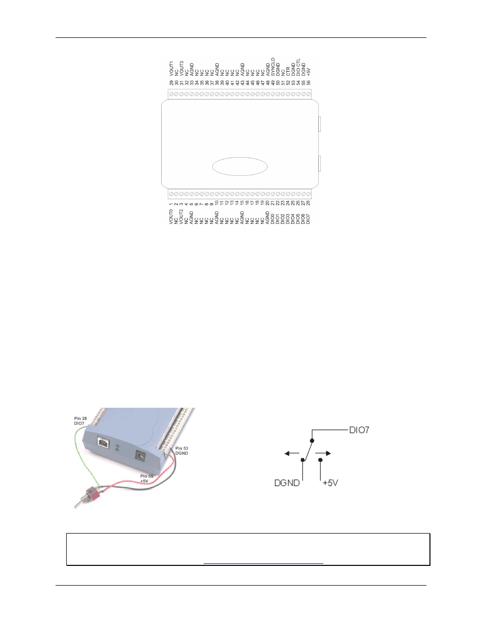
Figure 5. USB-3110 signal pin out
Analog voltage output terminals (VOUT0 to VOUT3)
The screw terminal pins labeled
VOUT0
to
VOUT3
are voltage output terminals (see Figure 5). The voltage
output range for each channel is software-programmable for either bipolar or unipolar. The bipolar range is
±10 V, and the unipolar range is 0 to 10 V. The channel outputs may be updated individually or simultaneously.
Digital I/O terminals (DIO0 to DIO7)
You can connect up to eight digital I/O lines to the screw terminals labeled
DIO0
to
DIO7
(pins 21 through 28).
You can configure each digital port for either input or output.
When you configure the digital bits for input, you can use the digital I/O terminals to detect the state of any
TTL level input. Refer to the switch shown in Figure 6 and the schematic shown in Figure 7. When the switch
is set to the +5 V USER input, DIO7 reads TRUE (1). If you move the switch to DGND, DIO7 reads
FALSE (0).
Figure 6. DIO7 detecting the state of a switch
Figure 7. Schematic showing DIO7 detecting the state of a switch
For more information on digital signal connections
For more information on digital signal connections and digital I/O techniques, refer to the Guide to Signal
Connections (available on our web sit