Measurement Computing USB-5201 Installation User Manual
Measurement Computing Hardware
DS USB-520x.doc
Document Revision 5, March, 2010
Copyright © 2006-2010 Measurement Computing Corporation
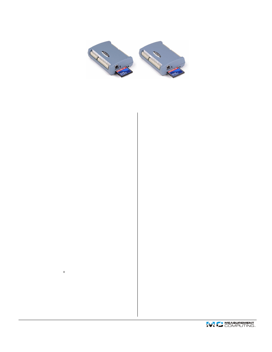
Notes on installing and using the USB-5201
and USB-5203 data logging devices
Thank you for purchasing the USB-5201 or USB-5203 device from Measurement Computing! Please read this sheet to help you set
up your new USB-based data acquisition and data logging device.
Use InstaCal to configure and test your device before you acquire and log data. After logging data, download and convert the data
from the memory card with TracerDAQ®. You can optionally use InstaCal to copy or convert data directly from the data logging
device.
Configuring channel sensors
1.
From the InstaCal main form, double-click on the name
of the device to open the
Board Configuration
dialog.
2.
Configure the sensor options for your data logger
channels.
USB-5203
: Select a sensor category using the
CH(n-n)
tabs for each pair of analog input channels
— choices are RTD, thermistor, thermocouple, and
semiconductor — and configure the settings that are
enabled for the selected sensor.
USB-5201
: Click on the
TC Type
tab and select a
thermocouple type for each analog input channel.
Configuring data logging options
1.
Click on the
Data Logger > Logger Data
tab and select
your data logging preferences:
Select the time format, time zone, and temperature
units to apply to converted files.
Format the flash storage (required for initial use):
Right-click on the device name in Windows
Explorer and select
Format
.
When operating a logging device installed with
firmware version 2.12 and earlier, click on the
Format Storage
button on the Logger Data tab.
2.
Click on the
Data Logger > Logger Setup
tab and select
your data logging options:
Set up each analog channel to log either temperature
measurements ( C) or raw resistance/voltage
measurements.
Select CJC data and/or time stamp data options to
log this data in addition to the channel
measurements.
Select the mode to start logging data.
Enter the interval (seconds) between samples and
the file number of the first file logged.
3.
Click on the
Data Logger > Alarm Setup
tab if you want
to set up the alarm options. Each digital I/O bit is
independently configurable as an alarm output. The input
to each alarm is one of the temperature input channels.
Set the following:
Select the channel number to use as the alarm input.
Set the output type (active high or low) of the alarm
bit when an alarm is triggered.
Select the threshold condition that triggers the alarm.
Specify the format of the logged alarm data
(temperature or raw). This setting is independent of
the format selected on the Logger Setup tab.
4.
To save the configuration settings to your hard drive,
click on the
Saved Configurations
tab and enter a name
to save the settings in the
Configuration Name
text box.
5.
Click on the
OK
button at the bottom of the Board
Configuration window. A dialog prompts you to write
the new configuration settings to the board.
6.
Click
Yes
to write the settings to the USB device. All
logging options are stored on the USB device in non-
volatile memory in EEPROM, and are loaded when you
connect external power to the device.
After configuring the sensor and logging options, the device
performs a self-calibration.
Testing the data logging device
Before logging data, verify the sensor options by running
InstaCal's Temperature Test. To run this test, select
Analog
from the
Test
menu on the InstaCal main form.
Logging data
External power is required to log data. Disconnect the USB
cable from the device, and connect the supplied external
power supply. The logging options that are stored on the
device are loaded. You are now ready to log data!
Document Outline
- Configuring channel sensors
- Configuring data logging options
- Testing the data logging device
- Logging data
- Ending a data logging session
- Disconnecting the device from the computer
- How data is stored on the memory card
- Downloading and converting data using InstaCal
- Importing and plotting .csv and binary data using TracerDAQ®
- Assigning a drive letter to the mass storage device