Analog output – Measurement Computing USB-7204 User Manual
Page 23
USB-7204 User's Guide
Specifications
23
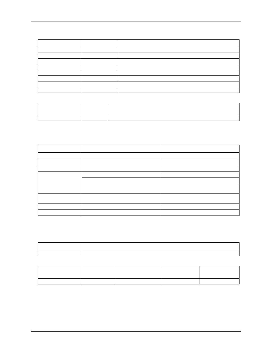
Table 6. Noise performance, differential mode
Range
Typical counts
Least significant bit
root mean square
(LSB
rms)
±20 V
2
0.30
±10 V
2
0.30
±5 V
3
0.45
±4 V
3
0.45
±2.5 V
4
0.61
±2 V
5
0.76
±1.25 V
7
1.06
±1 V
8
1.21
Table 7. Noise performance, single-ended mode
Range
Typical
Counts
LSB
rms
±10 V
2
0.30
Analog output
Table 8. Analog output specifications
Parameter
Conditions
Specification
Resolution
12-bits, 1 in 4096
Output range
0 – 4.096 V, 1 mV per LSB.
Number of channels
2
Throughput (Note 5)
Software paced
250 S/s single channel typ, system dependent
Single channel, continuous scan
10 kS/s
Dual channel, continuous scan, simultaneous
update
5 kS/s
Power on and reset
voltage
Initializes to 000h code
Output drive
Each D/A OUT
15 mA
Slew rate
0.8V/microsecond (µs) typ
Note 5:
Maximum throughput scanning to computer memory is machine dependent. The rates specified are for
Windows XP only. Maximum rates on operating systems that predate XP may be less and must be
determined through testing on your machine.
Table 9. Analog output accuracy, all values are (±)
Range
Accuracy (LSB)
0 V to 4.096 V
4.0 typ, 45.0 max
Table 10. Analog output accuracy components, all values are (±)
Range
% of FSR
Gain Error at FS (mV)
Offset (mV)
(Note 6)
Accuracy at FS
(mV)
0 V to 4.096 V
0.1 typ, 0.9 max
4.0 typ, 36.0 max
1.0 typ, 9.0 max
4.0 typ, 45.0 max
Note 6:
Negative offsets will result in a fixed zero-scale error or "dead band." At the max offset of 9 mV, any
input code of less than 0x009 will not produce a response in the output.