Measurement Computing DBK206 User Manual
Dbk206, P4-to-p1/p2/p3 adapter board, Overview
DBK206
P4-to-P1/P2/P3 Adapter Board
For Analog I/O, Digital I/O, & Pulse/Frequency
Overview …… 1
Connections …… 1
Note:
DBK206 provides: P1, P2, and P3 connectors and corresponding screw-terminal blocks
for use with DaqBook/2000 Series Devices, DaqBoard/2000 Series Boards,
and cPCI DaqBoard/2000c Series Boards.
This product is not used for LogBook applications.
Reference Notes:
In regard to calculating system power requirements refer to the DBK Basics section.
Chapter 2 includes pinouts for P1, P2, P3, and P4. Refer to pinouts applicable to your
system, as needed.
For a quick comparison of all DBK200 Series boards, refer to the DBK200 Series Matrix.
The matrix is located just before the DBK200 section.
Refer to the DaqBoard/2000 Series and cPCI DaqBoard/2000c Series User’s Manual
(p/n 1033-0901) or the DaqBook/2000 Series User’s Manual (p/n 1103-0901)
for information pertaining to those products, as needed.
Overview
DaqBoard/2000 Series and cPCI DaqBoard/2000c Series boards communicate [external from the host PC]
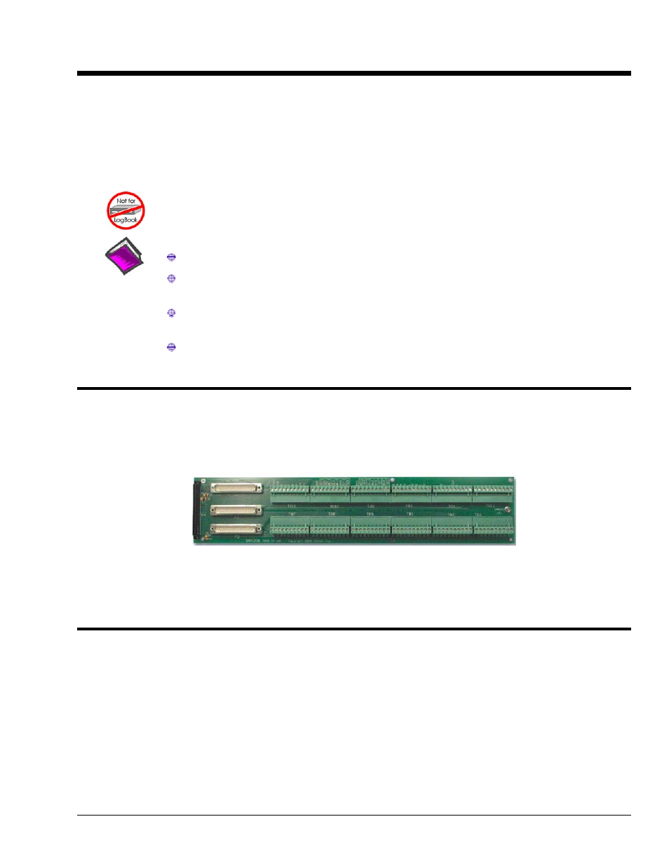
through a 100-pin P4 connector. The DBK206 provides a P1, P2, and P3 connector and corresponding
screw-terminal blocks. P1 is used for ANALOG I/O, P2 for DIGITAL I/O, and P3 for
PULSE/FREQUENCY (Digital and Counter/Timer) I/O.
DBK206, P4-to-P1/P2/P3 Adapter with Screw-Terminals
Note: The P1, P2, and P3 connectors discussed in association with DaqBook/2000 Series devices
DaqBoard/2000 Series boards and cPCI DaqBoard/2000c Series boards are subset connectors of the
100-pin P4 connector that is located on those boards. Chapter System Connections and Pinouts,
includes pinouts for P1, P2, P3, and P4.
Connections
The DBK206 is suitable for both analog and digital expansion. Signal connection to a DaqBook/2000
Series device, DaqBoard/2000 Series board, or to a cPCI DaqBoard/2000c Series board can be made as
follows:
• With cables connected to P1, P2, and P3 connectors, as applicable.
• With signal wires connected to the appropriate screw-terminal blocks (TB1 through TB12).
Note that the DBK206 board’s silkscreen clearly identifies all screw terminals.
• With a combination of the above two methods.
DBK Option Cards and Modules
987594
DBK206, pg. 1