Measurement Computing DBK208 User Manual
Dbk208, Relay carrier board, Overview
DBK208
Relay Carrier Board
For Opto-22 Compatible Solid-State-Relays
Overview …… 1
Warnings, Cautions, and Tips …… 3
Power …… 4
External Power Watchdog …… 5
Operation …… 5
Software Setup …… 7
DBK208 – Specifications …… 9
Note:
The DBK208 provides: (a) two P2 connectors, (b) footprints for sixteen optically-isolated Solid-
State-Relay (SSR) Modules, and (c) 16 dual-screw terminal blocks. DBK208 includes a 100-pin P4
connector for use with DaqBook/2000 Series Devices, DaqBoard/2000 Series Boards, and /2000c
Series Boards.
This product is not used with:
LogBook
DaqBook/100 Series devices
DaqBoard/100 (ISA-type) Series devices
Reference Notes:
In regard to calculating system power requirements refer to the DBK Basics section.
Chapter 2 includes pinouts for P1, P2, P3, and P4. Refer to pinouts applicable to your
system, as needed.
For a quick comparison of all DBK200 Series boards, refer to the DBK200 Series Matrix.
The matrix is located just before this DBK200 section.
Refer to the DaqBoard/2000 Series and cPCI DaqBoard/2000c Series User’s Manual
(p/n 1033-0901) or the DaqBook/2000 Series User’s Manual (p/n 1103-0901) for information
pertaining to those products, as needed.
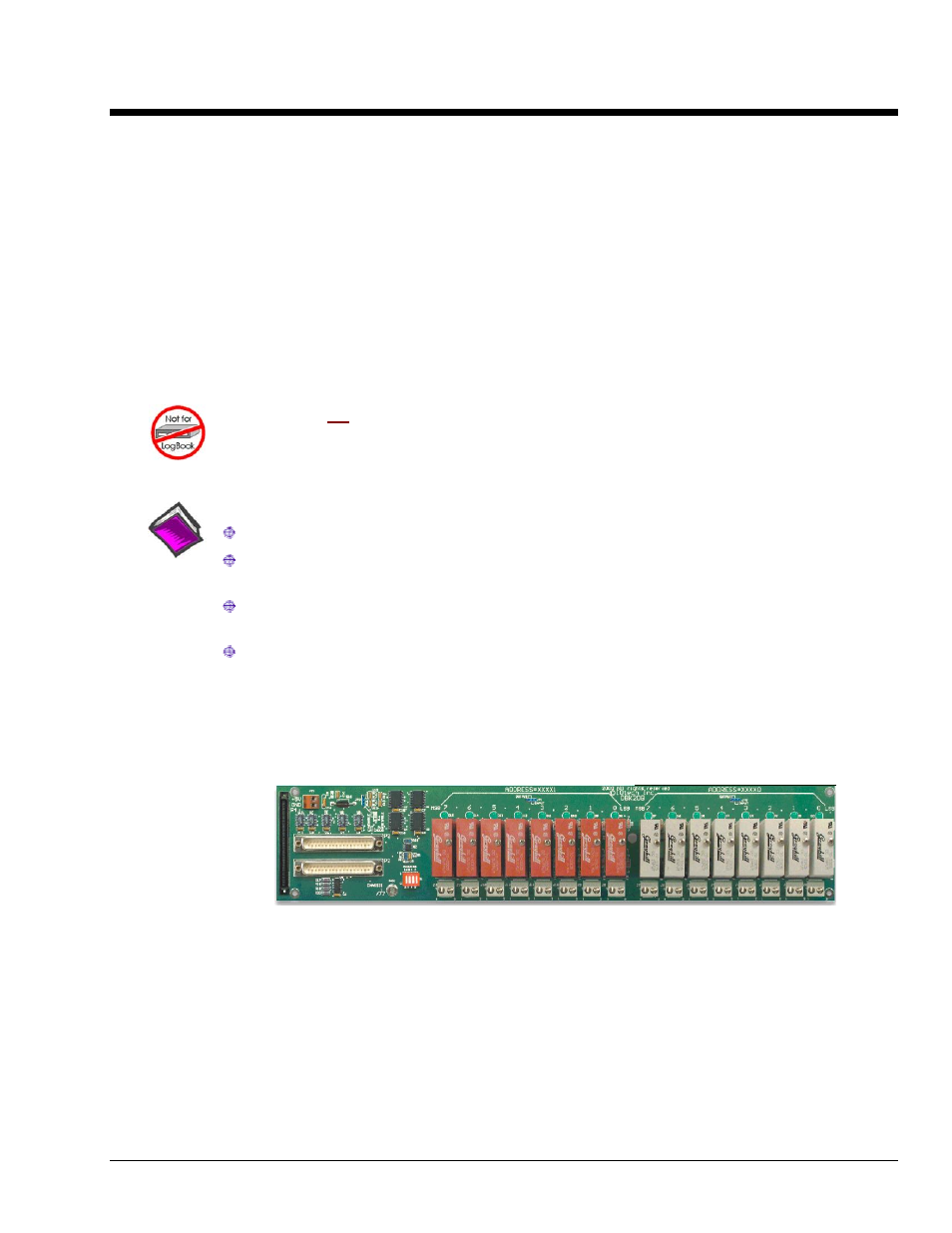
Overview
DBK208 Carrier Board for Opto-22 Compatible Solid-State-Relays
DaqBoard/2000 Series and cPCI DaqBoard/2000c Series boards communicate [external from the host PC]
through a 100-pin P4 connector. The P1, P2, and P3 connectors discussed in association with these boards
are subset connectors of the 100-pin P4 connector. Chapter System Connections and Pinouts, includes
pinouts for P1, P2, P3, and P4.
The information included in this section, when combined with that found in the related DBK option cards
and modules subsections should enable you to set up your desired configuration.
DBK208 is a two-bank carrier board for optically-isolated Solid-State-Relay (SSR) modules. Each bank
supports up to eight digital I/O modules. The banks can be independently set as “input” or “output” via
jumpers (JP0 for Bank 0, and JP1 for Bank 1). The I/O modules are industry standard Opto-22 compatible,
5-volt logic level modules.
DBK Option Cards and Modules
987594
DBK208, pg. 1