Terminal block connection warning, P1 connection – Measurement Computing DBK44 User Manual
Page 4
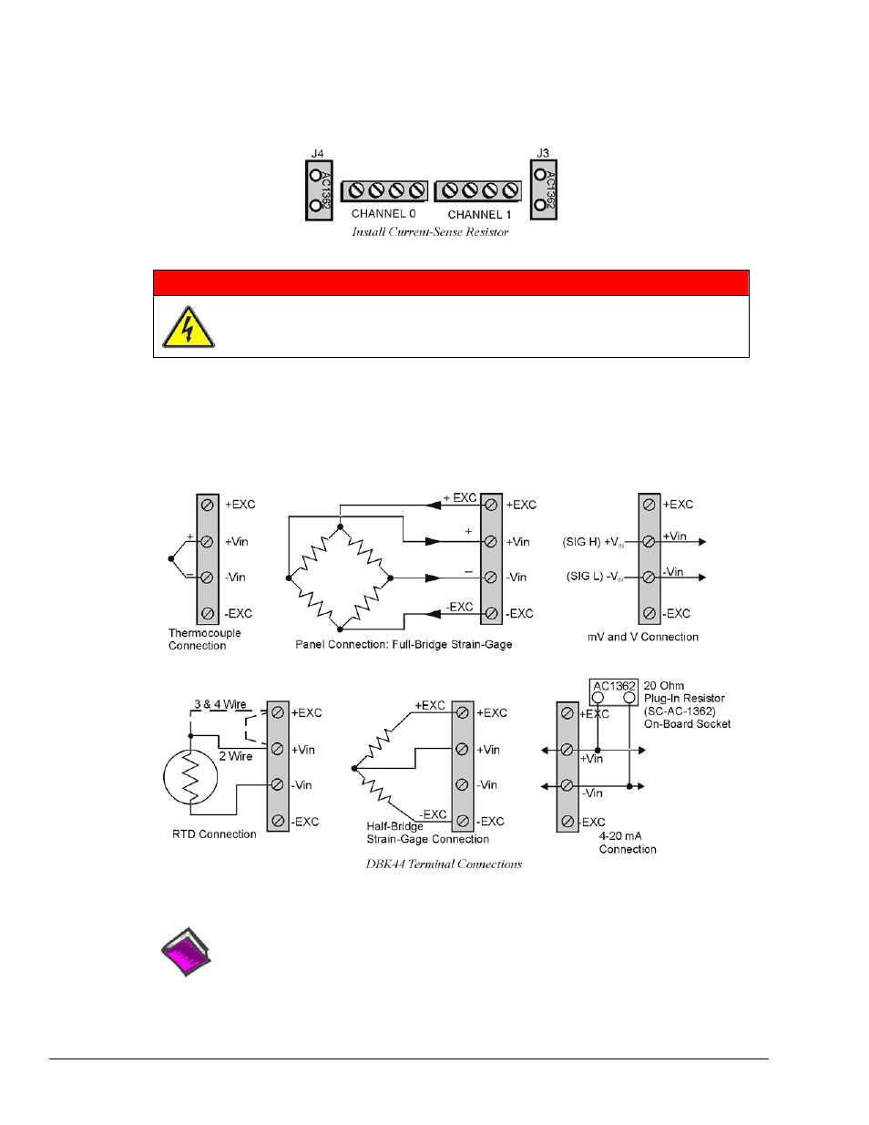
When installing current input modules (SC-5B32 series), be sure to install the current-sense resistor
(SC-AC-1362 shipped with the SC-5B32) in the resistor socket (J4 for ch 0, J3 for ch 1) near the input
screw-terminal block (see figure).
Terminal Block Connection
WARNING
Shock Hazard! De-energize circuits connected to the DBK44 before changing the
wiring or configuration. The DBK44 is designed to sense signals that may carry
dangerous voltages.
Input signals (and excitation leads) must be wired to the DBK44 via the 4-contact terminal blocks at the
end of the card. These terminal blocks connect internally to their corresponding signal conditioning
module. The terminal blocks accept up to 14-gage wire into quick-connect screw terminals that are labeled
as to their function. Each type of input signal or transducer (such as a thermocouple or strain gage) should
be wired to its terminal block as shown in the figure. Wiring is shown for RTDs, thermocouples, 20 mA
circuits, mV/V connections, and for full- and half-bridge strain gages.
P1 Connection
Reference Notes:
Chapter 2 includes pinouts for P1, P2, P3, and P4. Refer to pinouts applicable to your
system, as needed.
The DBK44 attaches to the LogBook’s or Daq Device’s P1 analog I/O connector. Connect the CA-37-x
accessory ribbon cable (with x indicating the number of cards to be connected) from P1 to the DB37
connector at the end of the DBK44 card.
DBK44, pg. 4
877095
DBK Option Cards and Modules