Measurement Computing DBK50 User Manual
Dbk50, Dbk51, Channel isolated
DBK50
and
DBK51
8-Channel
Isolated
Voltage Input Modules
Overview …… 1
Input Attenuation/Gain Factors …… 2
Hardware Setup …… 2
Signal-to-Module Connection …… 2
Module Configuration …… 2
DaqBook/100 Series & /200 Series and DaqBoard [ISA type] Configuration …… 3
DaqBook/2000 Series and DaqBoard/2000 Series Configuration …… 4
Software Setup …… 4
DBK50 and DBK51 – Specifications …… 4
Reference Notes:
o
Chapter 2 includes pinouts for P1, P2, P3, and P4. Refer to pinouts applicable to your
system, as needed.
o
In regard to calculating system power requirements, refer to DBK Basics located near
the front of this manual.
Overview
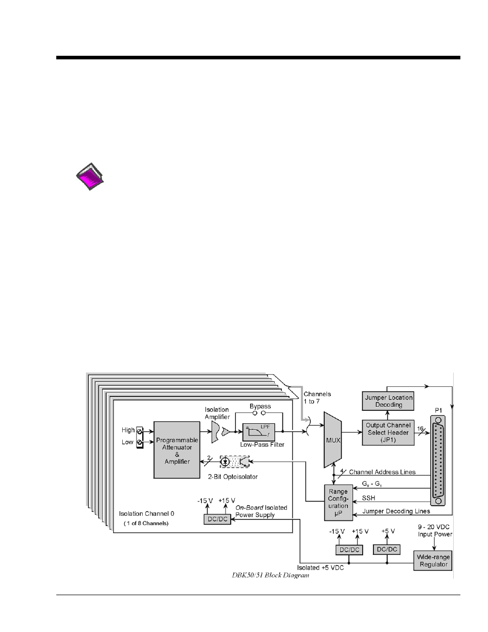
Except for their ranges, the DBK50 (high-voltage) and the DBK51 (low-voltage) are identical. Both have
eight channels isolated from themselves (750 V) and from the LogBook or Daq Device analog common
(1250 V). Each channel’s input impedance is over 10 M
Ω
to minimize loading of the circuit being
measured. Voltages can be read from DC to more than 20 kHz. One of three voltage ranges can be chosen
via software:
• for DBK50: ±10 V, ±100 V, or ±300 V.
• for DBK51: ±100 mV, ±1 V, or ±10 V.
With standard plug-in attenuator assemblies, the voltage ranges are interchangeable. The gain or
attenuation factor depends on the range, but the full-scale output for any range is +5 V.
Note: A fourth “range” delivers a shorted input voltage reading to allow offset compensation in some
applications.
DBK Option Cards and Modules
989594
DBK50 and DBK51, pg. 1