Measurement Computing DBK55 User Manual
Dbk55, Channel frequency-to-voltage input module
Advertising
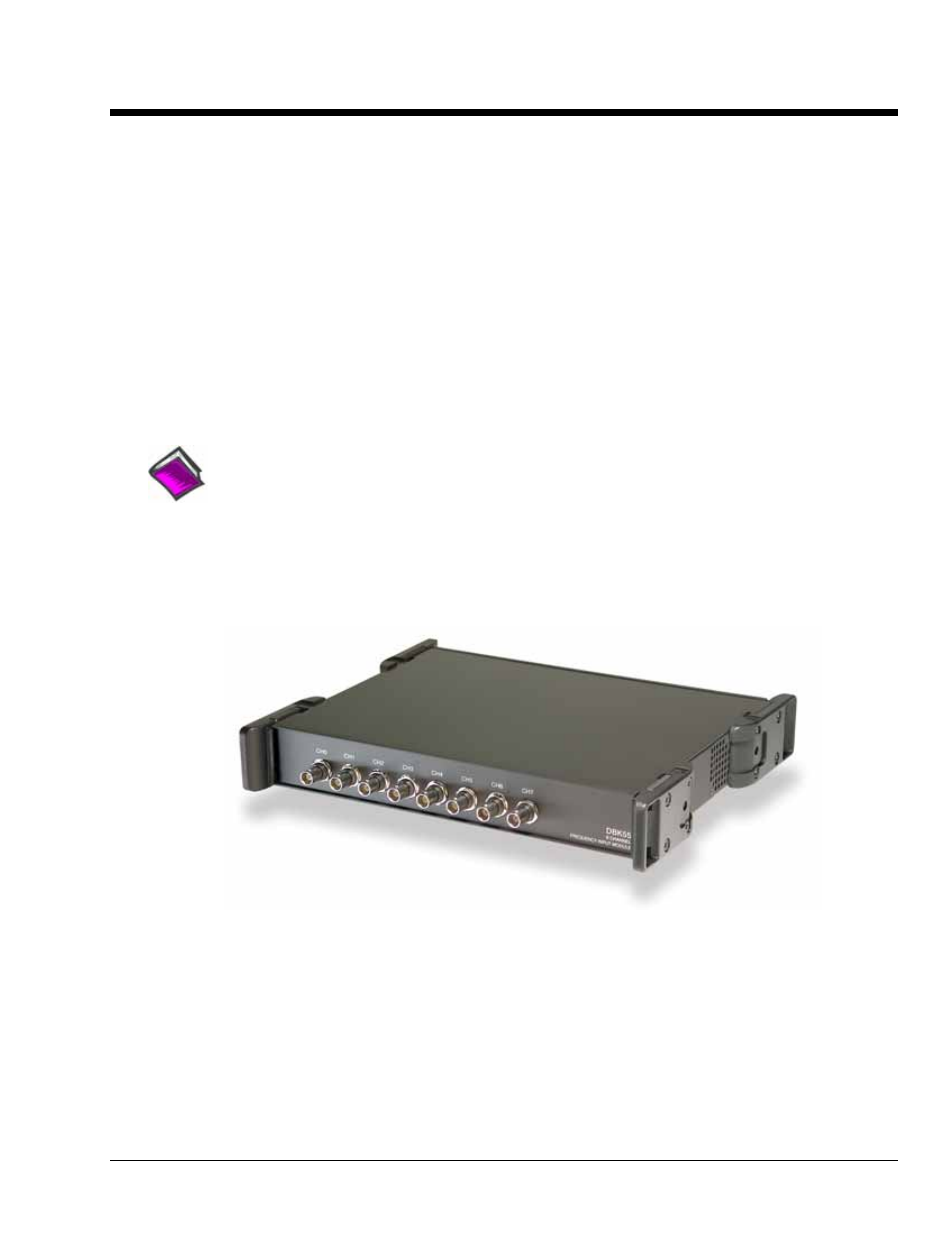
DBK55
8-Channel Frequency-To-Voltage Input Module
Features of the DBK55 …… 2
Input Signal Conditioning …… 3
Edge Selection …… 4
Debouncing …… 4
Frequency Measurement …… 5
D/A Conversion …… 6
Hardware Setup …… 6
Configuring the DBK55 Module …… 6
Configuring the Primary Data Acquisition Device …… 10
CE Compliance …… 10
Connecting the DBK55 to Signals and to the Primary Data Acquisition Device …… 11
Specifications…… 12
Reference Notes:
o
Chapter 2 includes pinouts for P1, P2, P3, and P4. Refer to pinouts applicable to your
system, as needed.
o
In regard to calculating system power requirements, refer to DBK Basics located near
the front of this manual.
DBK55 Module
DBK Option Cards and Modules
987693
DBK55, pg. 1
Advertising
Table of contents