Measurement Computing DBK60 User Manual
Dbk60, Slot expansion chassis with termination panels, Overview
DBK60
3-Slot Expansion Chassis with Termination Panels
Overview …… 1
Hardware Setup …… 2
1 – Turn off system power and disconnect DBK60 …… 3
2 – Remove the top cover (optional) …… 3
3 – Remove the card drawer …… 3
4 – Remove termination panels …… 3
5 – Determine power requirements …… 3
6 – Configure the chassis for power source …… 4
7 – Install a power card, if needed …… 5
8 – Configure the DBK cards …… 5
9 – Install the DBK cards …… 5
10 – Connect the internal signals …… 5
11 – Install the termination panels …… 5
12 – Install the card drawer …… 6
13 – Connect external signals …… 6
14 – Install the top cover …… 6
15 – Connect the DBK60 to the rest of your acquisition system …… 6
16 – Turn on system power and check operation …… 6
DBK60 – Specifications …… 6
Reference Notes:
o
Chapter 2 includes pinouts for P1, P2, P3, and P4. Refer to pinouts applicable to your
system, as needed.
o
In regard to calculating system power requirements, refer to DBK Basics located near
the front of this manual.
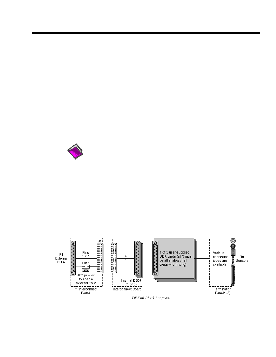
Overview
The DBK60 expansion chassis holds up to three analog DBK cards, or up to three digital DBK cards, and
provides termination panels with connectors for various sensors. Several DBK60 units can be linked
together and then to the primary acquisition device, e.g., a DaqBook, DaqBoard, or LogBook.
Splice plate kits can be used to stack multiple DBK60 units to the primary device.
DBK Option Cards and Modules
989594
DBK60, pg. 1