Source impedance and settling time, Reading error vs. source resistance – Measurement Computing DBK65 User Manual
Page 6
5. Using rosin core solder and proper soldering technique,
solder the resistor into position for the applicable
channel.
Be sure that the resistor leads are short
enough to avoid making contact with the metal
chassis
.
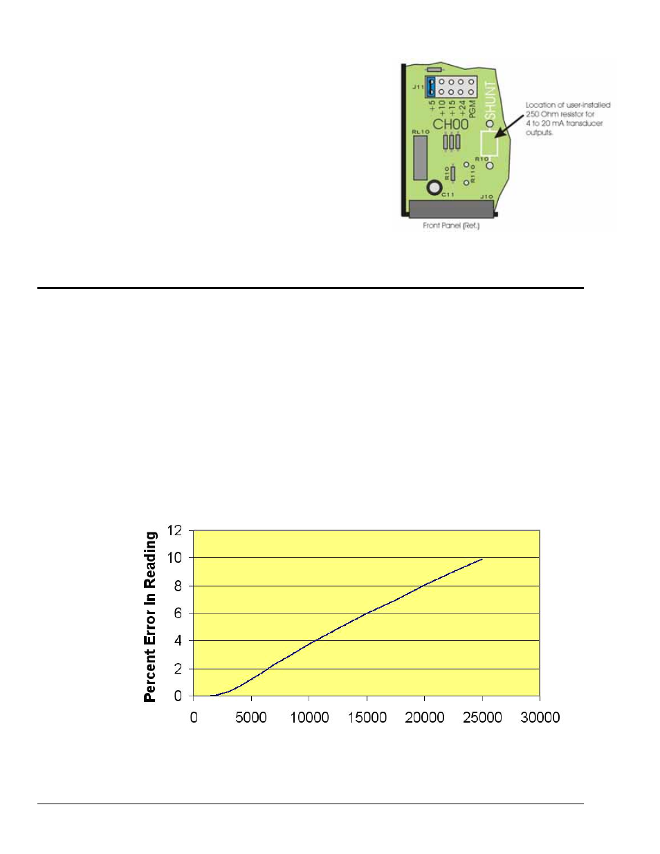
The figure to the right indicates the resistor location for
use with channel 0 (CH00). The location scenario is
similar for all 8 channels.
6. Re-install the top cover plate and secure it with the
4 screws that were removed in step 3.
Source Impedance and Settling Time
High speed multiplexing of signal sources with non-zero impedance will result in reading errors caused by
settling time. In the simplest form, a multiplexing system consists of a group of switches, with internal
resistance, and an output capacitance at the input of an amplifier feeding an A/D converter with a sample-
hold circuit on the input. During the short time a channel signal is connected to the A/D amplifier, the
signal must charge the output capacitance to the true value of the signal so that the sample-hold captures an
accurate value for the A/D converter to digitize. If the source has significant internal impedance the
voltage reading will be reduced.
Source impedance below 1000 ohms will create negligible error. Above 1000 ohms, the effects are
increasingly noticeable. An accurate source in series with a variable resistance will readily demonstrate
this. Although the effect is exponential, an easy reference point to remember is that 25K of source
impedance will result in approximately a 10% error.
Reading Error vs. Source Resistance
Source Resistance in Ohms
DBK65 pg. 6
987693
DBK Option Cards and Modules