Measurement Computing DBK85 User Manual
Dbk85, Channel differential voltage module
Advertising
DBK85
16-Channel Differential Voltage Module
Overview …… 1
Hardware Setup …… 2
Configuring the DBK85 Module …… 2
Configuring the Primary Data Acquisition Device ……3
CE Compliance …… 4
Connecting the DBK85 to Signals and to the Primary Data Acquisition Device …… 4
Software Setup …… 5
Specifications …… 6
Reference Notes:
o
Chapter 2 includes pinouts for P1, P2, P3, and P4. Refer to pinouts applicable to your
system, as needed.
o
In regard to calculating system power requirements, refer to DBK Basics located near
the front of this manual.
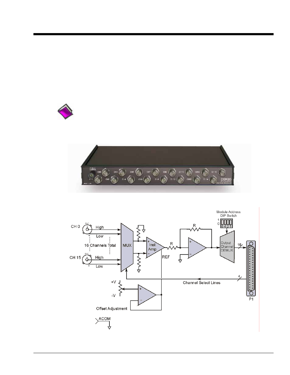
DBK85 Front Panel
DBK85 Block Diagram
DBK Option Cards and Modules
988793
DBK85 pg. 1
Advertising
Table of contents