Rear panel connectors, indicators, & power switch – Measurement Computing StrainBook/616 User Manual
Page 28
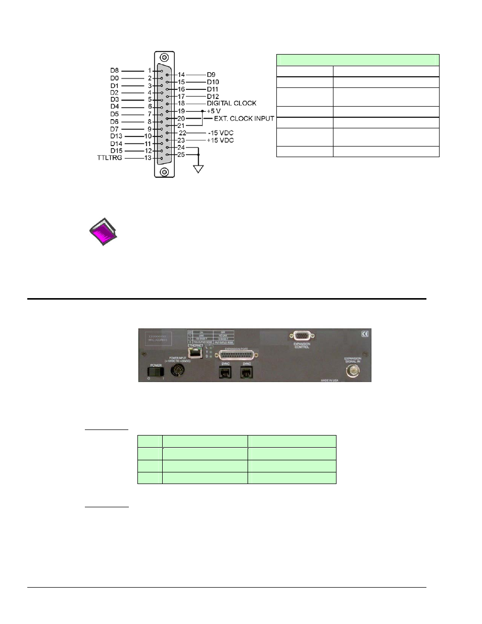
Digital I/O Connections, 16-Bit Mode
D0 through D15
High Speed Digital I/O data lines
TTLTRG
TTL trigger input
External Clock
Input
16 bit mode, read/write strobe,
Pin 20
+5 VDC
250 mA maximum
+15,-15 VDC
50 mA maximum (each)
Digital Clock
Pin 18, only used for WBK17
applications
Digital Grounds
Pins 24 and 25
DB25 Pinout, 16-Bit Mode
Reference Note:
In regard to 8-bit mode refer to Chapter 8, Digital I/O, TTL Trigger, and External Clock.
Chapter 8 repeats the 16-bid mode pinout and also discusses a dual-cable BNC option for
easily connecting the TTL Trigger and/or External Clock Input to the front panel DB25
connector.
Rear Panel Connectors, Indicators, & Power Switch
StrainBook/616 Rear Panel
The StrainBook/616 Rear Panel includes an LED legend in the upper left corner. Wording of the legend is
duplicated below. The rear panel also includes connectors, LED indicators, and a power switch.
LED Legend: Applies to the three LEDs located between the Ethernet Port and the Expansion Port.
LED
ON
OFF
L
LINK
NO LINK
T
100 BASE-T
10 BASE-T
D
FULL-DUPLEX MODE
HALF-DUPLEX MODE
ETHERNET: The 10/100BaseT Ethernet port can connect to the Ethernet port of the host PC, or to an
Ethernet network. Either of two Ethernet patch cables may be used to make the connection. CA-242 is a
1.5 foot cable. CA-242-7 is a 7-foot cable. Note that the Ethernet connector has two built in LEDs that
indicate traffic flow. These are discussed with the three other Ethernet-related LEDs. Note that the
Ethernet cable length must be <10m in order for the system to be CE Compliant.
3-2 Connectors, Indicators, and Cables
967794
StrainBook/616 User’s Manual