Measurement Computing WBK14 User Manual
Page 2
WBK14, pg. 2
988396
WBK14, Dynamic Signal Input Module
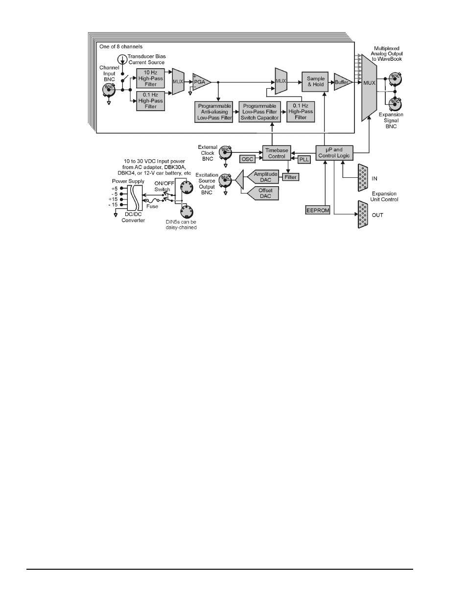
WBK14 Block Diagram
Current Source
WBK14 provides constant current to bias ICP transducers. Two current levels (2 mA or 4 mA) with
voltage compliance of 27 V can be selected via software. The bias current is sourced through the center
conductor of a coaxial lead and returns to the WBK14 by the outer conductor. The output impedance is
larger than 1 M
Ω and presents virtually no loading effect on the transducer’s output. For applications that
do not require bias, the current source can be removed from the BNC input by opening a relay contact.
The current sources are applied to (or removed from) the input in channel groups of two; i.e.,
channels 1-2, 3-4, 5-6, 7-8.
High-Pass Filters (HPF)
Each WBK14 channel has three High-Pass Filters (HPFs) with a 3-dB cut-off frequency (Fc). Two filters
are at 0.1 Hz and the other is 10 Hz. The 0.1-Hz HPF filters are single-pole RC filters. They are primarily
used to couple vibration signals. The 10-Hz HPF is a 2-pole Butterworth type that can be used to couple
acoustic signals or attenuate setup-induced low-frequency signals; since these can reduce the dynamic range
of the measurement (for example when using tape recorders as signal sources).
Programmable Gain Amplifier (PGA)
The HPF removes the DC voltage from the input signal. A PGA amplifies the AC voltage with flat response
up to 500 kHz. Each channel has a PGA with programmable gains (1, 2, 5, 10, 20, 50, and 100) and a
software-controlled DAC for offset nulling. The WBK14 measures only bipolar signals up to 5 V peak.
Programmable Low-Pass Anti-Aliasing Filter
The first filter stage is a programmable 2-pole continuous-time low-pass filter. The filter provides more than
65 dB alias protection to the next filter stage. In addition, it fine-tunes the phase shift of the channel to
optimize the phase-matching between channels. At calibration, the phase shift of each channel is measured
and stored in an EEPROM that is read at configuration.