Measurement Computing DBK34 User Manual
Dbk34, Vehicle ups module, Overview
DBK34
Vehicle UPS Module
Overview …… 1
Hardware Setup …… 2
Configuration …… 2
Connection …… 3
DBK34 Operation …… 3
Environmental Concerns …… 4
Fuse Replacement …… 4
DBK34 – Specifications …… 5
DBK34 is similar to DBK34A in appearance and operation; but there are differences. Before
proceeding with this section, verify that your device is a DBK34. If your device has an “A”
suffix, use the document module regarding the DBK34A UPS /Battery Module instead of this
document module.
Reference Notes:
o
Chapter 2 includes pinouts for P1, P2, P3, and P4. Refer to pinouts applicable to your
system, as needed.
o
In regard to calculating system power requirements, refer to DBK Basics located near
the front of this manual.
Overview
The DBK34 can power a data acquisition system in portable and in-vehicle applications (both 12 and 24 V
systems). Power storage capacity is 5 A-hr @ 12 VDC or 2.5 A-hr @ 24 VDC.
For reliable data acquisition in a vehicle, the DBK34 provides clean and consistent operating power:
• Prior to engine/generator start
• During engine start-up (battery sag due to the high-current demand of starter motor and
solenoid)
• After engine turn off.
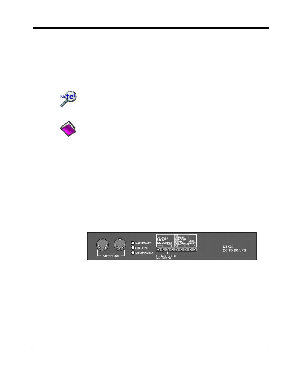
DBK34 Front Panel
The DBK34 contains two sealed-lead rechargeable batteries and associated charging circuits and current
indicators. Typically, these batteries can last more than 500 full cycles and up to 10 years standby lifetime
at room temperature. Recharging is fast, and extreme temperature performance is good. The DBK34 can
be used with the LogBook, DaqBook, WaveBook, and related DBKs and WBKs. The unit’s rugged metal
package has a compatible 8×11” footprint for convenient stacking with dual-lock tabs and optional splice
plates and handles for carrying.
DBK Option Cards and Modules
879795
DBK34, pg. 1