Measurement Computing NDTRELAY2 User Manual
Ndtrelay2, Installation guide, Introduction
NDTRELAY2, Installation Guide
958596
p/n
1099-0901
rev.
2.0
NDTRELAY2
Installation
Guide
Introduction
The NDTRELAY2 is an RS-232 relay interface that features: 8 Normally Open Contact Outputs, 4 Digital Inputs, and
16-Bit Contact or TTL Input Event Counters.
The NDTRELAY2 communicates via a standard RS-232 Port, using a three-wire interface. The signals used are
Received Data (RC), Transmitted Data (TX), and Ground (GND).
When added to an IOtech Non-Destructive Test system (NDT), or to an IOtech Temporary Online Monitoring and
Analysis system (TOMAS), the NDTRELAY2 allows the associated software (eZ-NDT or eZ-TOMAS) to read external
discrete signals and open and close relays relative to specified software events. The software controls all functions of the
NDTRELAY2. No user programming or setup is required. Refer to your eZ-NDT or eZ-TOMAS documentation for
instructions on how to perform NDTRELAY2 I/O operations.
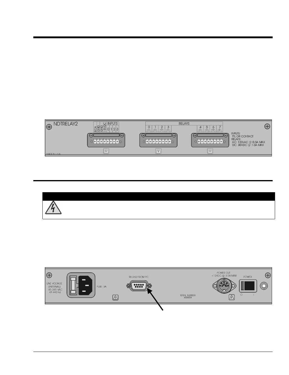
NDTRELAY2, Input and Relay Connectors
Connecting the Communication Cable
WARNING
WARNING
WARNING
WARNING
Always turn OFF the NDTRELAY2 and unplug it before making or breaking any connections; or
before opening the unit for any reason. Failure to do so could result in electric shock, or equipment
damage.
With power to the NDTRELAY2 turned off (0), connect a null-modem cable to the unit’s DB9S connector. The
connector is labeled “RS-232 From PC.” Connect the other end of the null-modem cable to the host PC’s COM Port.
Note that IOtech’s PC/AT/XT null-modem serial cable, p/n CA-47, makes a good communication cable.
DB9S - Connects to the PC’s COM Port via a null-
modem cable, such as IOtech’s p/n CA-47.
NDTRELAY2, Power and Communication Connectors