Watchdog timer enable/disable (jp8), Time base selection (jp9), Hardware installation – Measurement Computing TempBook rev.4.0 User Manual
Page 22: Rechargeable battery module (dbk30a)
2-4 Installation, Configuration, and Calibration
04-25-01
TempBook User’s Manual
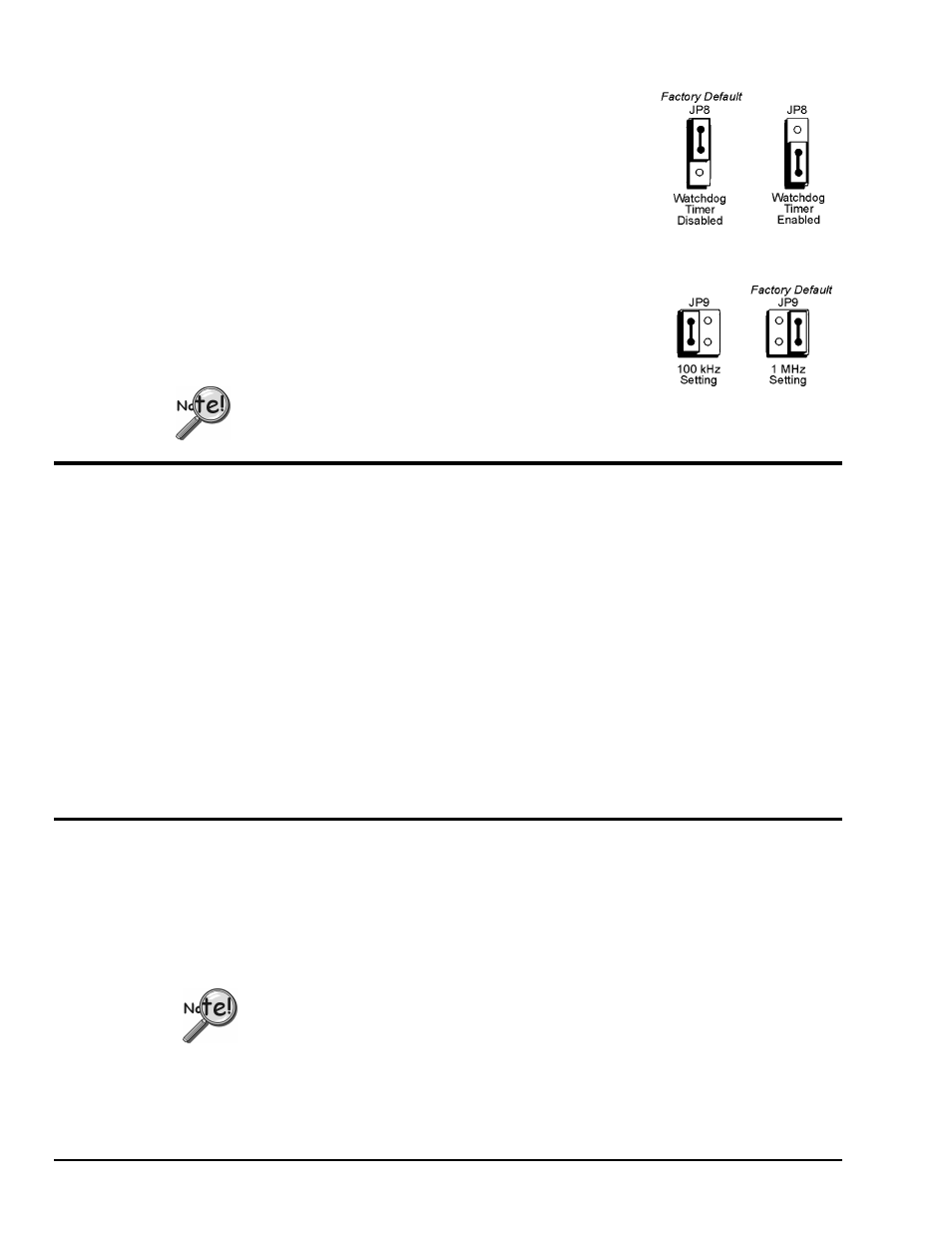
Watchdog Timer Enable/Disable (JP8)
This 3-pin header allows the elective use of the TempBook watchdog timer
function. If using a printer with the TempBook, the watchdog timer should
be enabled to allow the TempBook to be most reliably reset by the host
computer. Note that enabling the watchdog timer might impede background
measurements. If the user is not going to attach a printer, the timer is
optional. The default setting is Watchdog Timer Disabled. To enable, place
the shunt jumper in the enabled position as shown in the figure. To disable,
place the jumper in the disabled position, as shown.
Time Base Selection (JP9)
This 2×2 header allows the user to select one of two oscillator derived
frequencies to be applied to the pacer clock (8254 P1 & P2). The pacer clock
sets the interval between scans in continuous trigger mode. The two
frequencies are 1 MHz and 100 kHz. The most useful range of clock output
frequencies [for the typical user] is provided by the default, 1 MHz setting.
DaqView only supports a setting of 1 MHz, which is the factory default.
Hardware Installation
Connect the TempBook to any PC parallel printer port (female DB25) by unplugging the printer cable and
plugging the male end of the supplied cable (CA-35) into the computer and the female end into the mating
connector on the TempBook. Any printer port (LPT1, LPT2, or LPT3) may be used but should be noted
for use in software installation.
TempBook allows for LPT pass-through for simultaneous data acquisition and printer operation. When
using a printer in the system, attach the original printer cable male DB25 into the mating connector on the
TempBook.
The TempBook may be powered by the supplied AC adapter that plugs into any standard wall outlet or
from an isolated 9-20 VDC source of 1-2 A.
If using the power adapter, plug it into a 120 VAC outlet, and attach the low voltage end to the jack on the
TempBook. Turn ON the power switch, and the POWER LED should be on.
At power-on, the printer should behave normally and can be checked by issuing a PRINT SCREEN
command (or any other convenient method of checking the printer). (Installation of the software will be
necessary before the TempBook can perform any functions.)
Rechargeable Battery Module (DBK30A)
For portable applications where external AC or DC power is not available, the DBK30A rechargeable
nickel cadmium battery module can be used with the TempBook/66. This module is housed in a rugged
metal package that is the same size as the TempBook. It also comes with high-strength Velcro tabs that
allow convenient mounting underneath the TempBook/66.
The DBK30A has two modes, the 14 VDC default and the 28 VDC mode. An internal slide-switch
determines the mode.
Only the 14VDC mode of the DBK30A is to be used with the TempBook/66.
The 14VDC operating mode provides 14.4 VDC at 3.4 A-Hr. This setup can power the TempBook for 3 to
6 hours depending on the application. The battery module has built-in automatic battery-charging circuits,
which quickly and safely recharge the internal batteries when connected to the supplied AC adapters. The
only requirement for trouble-free operation is for the user to fully charge the battery module before
attempting to use it.