5 channel configuration switch, Channel configuration switch, 6 connecting the rtd to the screw terminals – Measurement Computing CIO-EXP-RTD16 User Manual
Page 19
5.5 CHANNEL CONFIGURATION SWITCH
RTD connections may use 2, 3, or 4 wires coming from the probe. The three-wire connection is the
most common. The purpose of the three-wire connection is that the circuit will null-out resistance
variations in the connecting wires. A four-switch DIP switch block labeled INPUT CONFIG must be set
to match the number of wires connecting to each RTD. There is one switch block per RTD.
RTD Type
INPUT CONFIG Switch Settings
2 Wire
4 & 4 ON; 3 & 3 OFF
3 Wire
3 & 3 ON; 4 & 4 OFF
4 Wire
4 & 4 ON; 3 & 3 OFF
3
4
3
4
O
N
INPUT CONFIG
3
4
3
4
O
N
0
1
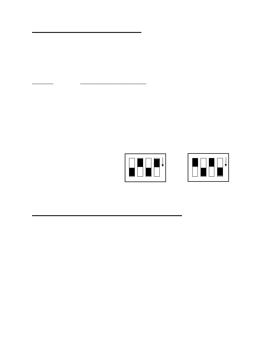
Set for 2 or 4-Wire Connection
Set for 3-Wire Connection
Channel Configuration Switch
Associated with each RTD is an
INPUT CONFIGuration switch. The
switch is used to configure the input
circuit for 2, 3, or 4 wire connections
(Figure 5-3).
Two and four-wire connections share
the same switch position. Set both
‘4’ switches ON and set both ‘3’
switches OFF.
For three-wire connection, set both
‘3’ switches ON and set both ‘4’
switches OFF.
Figure 5-3. Input Configuration Switches
5.6 CONNECTING THE RTD TO THE SCREW TERMINALS
The connections made to the screw terminal depend on the type of RTD you are using. The inputs of the
CIO-EXP-RTD16 are designed to provide the excitation and signal conditioning required to use RTDs.
An RTD may have 2, 3, or 4 wires that connect to the CIO-EXP-RTD16. Figures 5-4, 5-5, and 5-6 show
the three types of RTD connections and how to connect them to the input channels.
15