Meinberg TCR511PEX User Manual
Page 10
10
Pulse outputs
The module TCR511PEX generates pulses at change of second (PPS) and change of
minute (PPM). The PPS signal is available with TTL (0/+5V) or RS-232 (-3..12V/
+3..12V) level, the PPM signal with TTL level only. If required, DIP-switches can be set
up to direct the pulses to a corresponding pin of the D-Sub-connector in the bracket.
Asynchronous serial port
TCR511PEX provides an asynchronous serial interface (RS-232) called COM0. The
serial port sends a Standard Meinberg Time string either once per second, once per
minute or on request with ASCII ‘?’ only. The format of this telegram is described in the
‘Technical Specifications’. The transmission speed and the framing can be set via the
PCI-Express bus by using the shipped monitor software. Furthermore, the serial
interface COM0 is used for a potential firmware update.
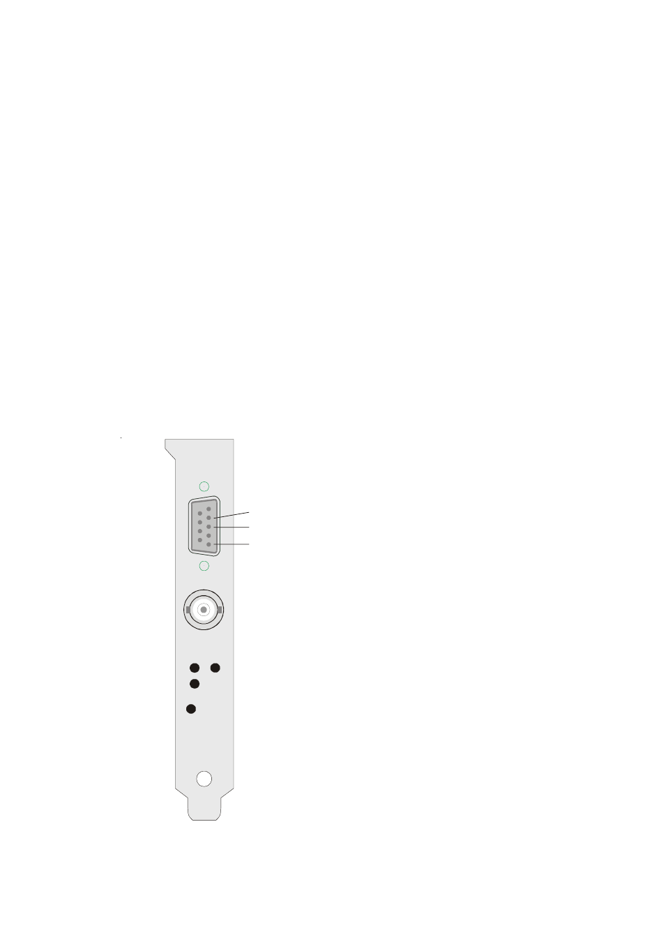
Connectors and LEDs in the bracket
The bracket of the board includes the BNC-
connector for the amplitude modulated time co-
des, three LEDs, a key for activating the Boots-
trap-Loader and a 9 pin D-Sub-plug.
The LEDs signal the status of the IRIG recei-
ver. The upper, red LED is switched on whene-
ver the internal timing of TCR511PEX is in
holdover mode. This state arises after power up
and if an error in the IRIG telegram is detected.
This LED changes state only at change of
minute.The central, green LED is switched on if
the IRIG receiver detects a correct telegram at its
input. If the below, green LED (Lock) is
switched on, the internal timing of TCR511PEX
is synchronized to the received IRIG code by a
PLL (Phase Locked Loop).
Pressing the hidden key BSL is required for
activating the Bootstrap-Loader before updating
the firmware.
antenna
Code
Lock
holdover
BSL key
RxD
TxD
GND