Led indicators – Microsens MS655100PX-48 User Manual
Page 8
5
LED Indicators
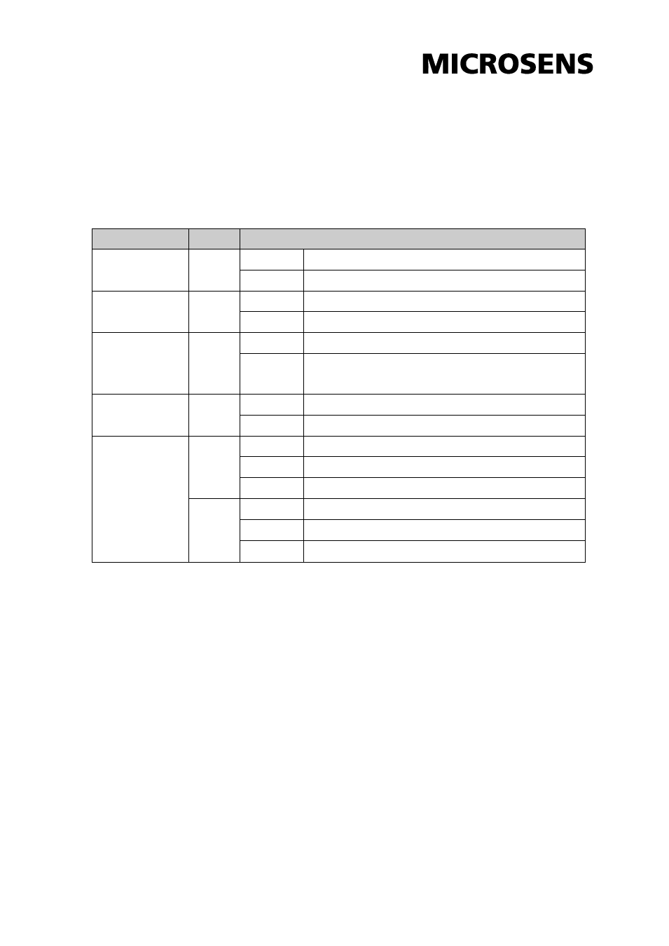
The diagnostic LEDs located on the front panel of the industrial switch provide real-time
information of system and optional status. The following table provides the description of
the LED status and their meanings for the switch.
LED
Color
Description
P1
Green
On
Power input 1 is active
Off
Power input 1 is inactive
P2
Green
On
Power input 2 is active
Off
Power input 2 is inactive
Fault
Red
On
Power input 1 or 2 has failed
Off
Power input 1 and 2 are both functional, or no power
inputs
FWD (1 ~ 4)
Green
On
The port is supplying power to the powered-device
Off
No powered-device attached or power supplying fails
1 ~ 5 (RJ-45)
Green
(Upper
LED)
On
Connected to network
Flashing
Networking is active
Off
Not connected to network
Amber
(Lower
LED)
On
Full-duplex link
Flashing
Collision occurs
Off
Half-duplex link or link down