Testing the gun – MK Products Prince XL Fronius Com ACWC User Manual
Page 17
Prince
®
XL Fronius Compatible Gun Owner's Manual - Page 10
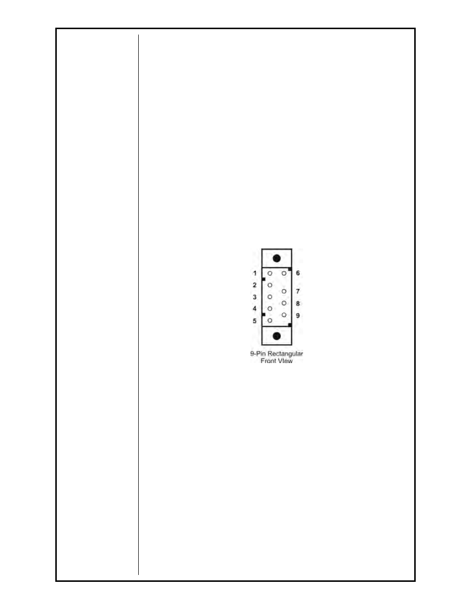
Testing The Gun
Reference the 9-pin rectangular diagram
on the Prince XL
Fronius Compatible
electrical diagram
for information about pin-outs and locations.
Motor Check
Remove the connector from the cabinet.
Using the 9-pin connector, check the resistance across pins
“1” and “6”
(motor leads). The resistance across the motor should be between
5 - 10
ohms as the potentiometer is turned.
If an open circuit or short exist, check the motor leads and motor
independently.
Testing the Gun Potentiometer
Using the 9-pin connector, check the resistance across pin
“3” (wiper) and
pin
“2”. The resistance should vary from 0 - 5K ohms as the potentiometer
is turned.
Check the resistance across pin
“3” (wiper) and pin “7”. The resistance
should vary from
5K - 0 ohms as the potentiometer is turned.
Testing the Micro Switch
Using the 9-pin connector, check for continuity across pins
“9” and “5” when
the trigger is pressed.