Montigo IOSK6 User Manual
Installation instruction kit part no. iosk6
Follow the instructions for the unit installation in the up to Step 1 on
Page 7 of the installation guide.
The unit is in place with the screws removed as illustrated there.
STEP 1: Back frame the unit with the metal header supplied by Montigo
above the unit and either combustible or non-combustible framing to the
sides and bottom maintaining clearances as shown and ensuring the
gallvanized apron (Fig 1, Part No. 620-482) can be attached to the framing.
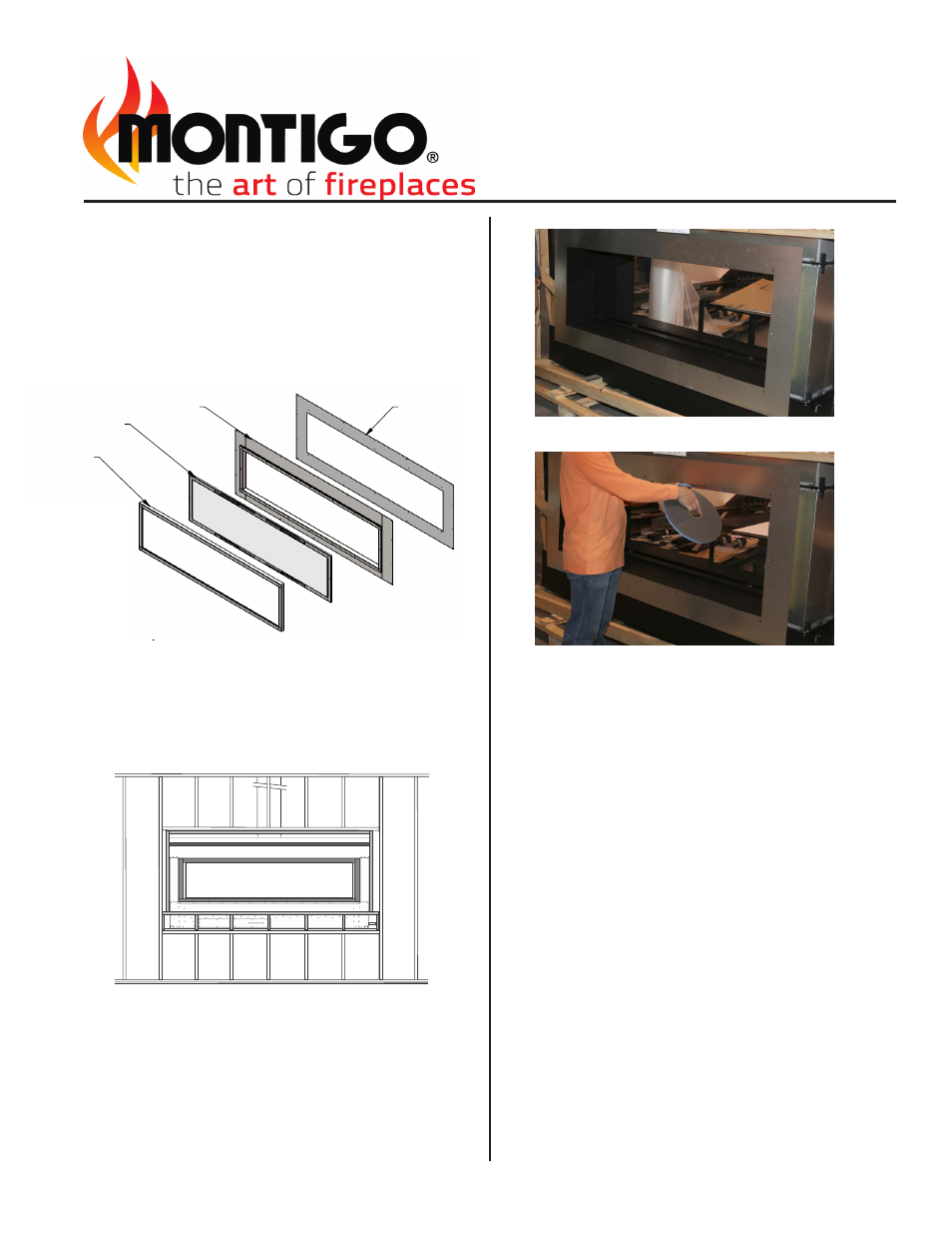
Figure 1: Indoor/ Outdoor Sealing Kit Ccmponents
Figure 2: Backframe unit
CLEARANCE TO COMBUSTIBLES:
6" Top, 3" each side, 3" bottom from the protruding window box.
Figure 3: Attach galvanized apron to unit
STEP 4: Attach the stainless steel frame (Fig. 1, Part No. IOSK6-A01)
to the galvanized frame lining up the holes around perimeter. Secure in
place through holes across the top and down the sides. Do not secure
the bottom flange.
STEP 5: Apply approved waterproofing membrane over the flange of
the frame on the top and sides and under the flange of the frame at
the bottom. The membrane should overlap the frame approximately 2"
around the perimeter.
STEP 6: All facing materials may now be installed over the frame.
BE CERTAIN TO MAINTAIN 6" ABOVE AND 3" ON SIDES AND BOTTOM
TO ANY COMBUSTIBLE MATERIAL
STEP 2: Place the galvanized apron and attach to the unit using the 6
screws removed from the unit face, Figure 3.
STEP 7: Mount the framed glass (Fig 1, IOSK6-A02) onto the unit and
secure in place first with only the two side screws.
STEP 8: Place the Galvanized strips (4 supplied) at each corner lining up
screw holes and secure both the strips and the framed glass to the unit.
STEP 9: Attach the stainless steel trim (Fig1, IOSK6-A03), by placing it
on and ensuring the magnets catch the previously placed galvanized strip.
Figure 4: Install silicone gasket
STEP 3: Install the silicon gasket material (supplied by Montigo) in one
continuous strip with the joint at the bottom, Figure 4.
Indoor / Outdoor Sealing Kit For R620 ST
Use this instruction in conjuction with unit
instruction manual (Doc. XG0773)
Installation Instruction
Kit Part No. IOSK6
85.25
30.12
18.79
21.80
73.92
76.94
2.90
ISOMETRIC VIEW
(NTS)
IOSK6-A03
IOSK6-A02
IOSK6-A01
620-482
ITEM NO.
PART NUMBER
DESCRIPTION
QTY.
REV.
1
620-482
BACK PLATE, IOSK6
1
A
2
IOSK6-A01
OUTER FRAME, IOSK6
1
A
3
IOSK6-A02
DOOR ASSEMBLY, IOSK6
1
A
4
IOSK6-A03
DOOR TRIM ASSEMBLY, IOSK6
1
A
NTS
SIZE DWG. NO.
A
REV.
SHEET 1 OF 1
WEIGHT:
IOSK6
FINISH
MATERIAL
DIMENSIONS ARE IN INCHES
TOLERANCES:
FRACTIONAL
1/32"
TWO PLACE DECIMAL
.015"
THREE PLACE DECIMAL
.005"
ALL BENDS ARE ASSUMED
TO BE 90 UNLESS NOTED
OTHERWISE.
CHECKED BY
DRAWN BY
LF
DATE
NAME
A
12/2/2010
INDOOR OUTDOOR SEALING KIT FOR R620
THE INFORMATION CONTAINED IN THIS DRAWING IS THE SOLE PROPERTY OF CANADIAN HEATING PRODUCTS. ANY REPRODUCTION IN PART OR AS A WHOLE WITHOUT THE WRITTEN PERMISSION OF CANADIAN HEATING PRODUCTS IS PROHIBITED.
PROPRIETARY AND CONFIDENTIAL
Z:\CADD\2007 CADD\Standard\Residential C-Vew\RVIEW IOK\R620IOK\IOSK6
Thursday, December 02, 2010 1:33:16 PM
SCALE