Installation, Optional fan kit, General information – Montigo RFK3002R User Manual
Page 2
Installation
Page 2
XT0019 - 150324
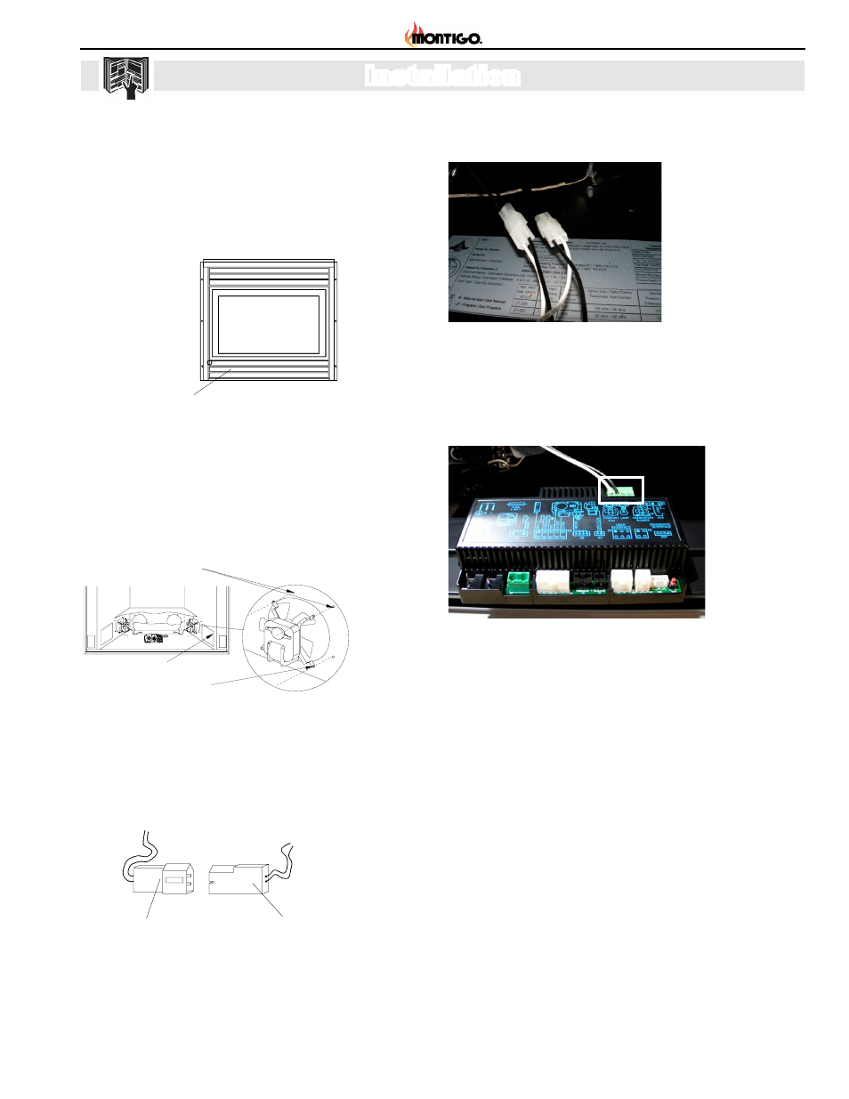
3. Electrical Connections
• Plug each of the fan motor connectors into a quick connector
on the wire harness.
Figure 3
Accessing control compartment.
• Connect the other end of the fan harness to control module
connection X10.
Figure 4
Cutaway view of control compartment showing fan
motor installation.
Figure 5
Electrical Connections.
4. Operation
• Turn on electical power at the breaker or fuse.
• Using the remot control, turn the fans on and adjust speed
as required (follow instructsions in XG0677 - Proflame 2
Operating instructions.
2. Fan Motor Installation
• Install each fan motor with the blades facing the 4" round fan
opening. Attach the mounting legs by screwing into the pilot
holes around the fan opening. Spin the fan blades by hand
to ensure they don't hit the fan opening. (See Figure 4.)
Optional Fan Kits
Optional Fan Kit
General Information
KIT #
Description
Models Used With:
RFK1002 2 fan kit, manual control
B34-DV, B34-DV-2
C34-DV, C34-VF
RFK1003 2 fan kit, heat-activated control
B34-DV, B34-DV-2
C34-DV, C34-VF
C38-DV
RFK1006 4 fan kit, manual control
C38-DV, C42-DV
RFK1007 4 fan kit, heat-activated control
C38-DV, C42-DV
RFK1008 4 fan kit, manual control
M38DV-ST
RFK1009 4 fan kit, heat-activated control
M38DV-ST
Before You Begin
Please read all instructions carefully.
We strongly recommend that all electrical service work be
performed by a qualified electrical contractor.
Check to ensure that all components required for installation
are included in your package.
Pull trim outwards
from bottom
Trim
Retainer clip
Control compartment
Figure 1. Removing the lower horizontal trims.
Installation
Accessing the Control Compartment
Remove the lower horizontal trims by placing your fingers under
bottom edge of trim next to retainer clips and pull outward. (See
Inset, Figure 1.)
Install each fan motor with the blades facing the 4" round fan
opening. Attach the mounting legs by screwing into the pilot holes
around the fan opening. Spin the fan blades by hand to ensure
they don't hit the fan opening. (See Figure 2.)
Fan Motor Installation
Figure 2. Cutaway view of control compartment showing fan
motor installation.
Pilot Holes
Mounting Legs
Access for
electrical connections
wire harness connector
fan motor
connector
Electrical Connections
Plug each of the fan motor connectors into a quick connector on
the wire harness. See Figure 3.
115/1/60 Supply
G
L1 L2
Figure 3. Electrical Connections.
XG0630 - Rev. 05/99
Page 1 of 2
Optional Fan Kits
Optional Fan Kit
General Information
KIT #
Description
Models Used With:
RFK1002 2 fan kit, manual control
B34-DV, B34-DV-2
C34-DV, C34-VF
RFK1003 2 fan kit, heat-activated control
B34-DV, B34-DV-2
C34-DV, C34-VF
C38-DV
RFK1006 4 fan kit, manual control
C38-DV, C42-DV
RFK1007 4 fan kit, heat-activated control
C38-DV, C42-DV
RFK1008 4 fan kit, manual control
M38DV-ST
RFK1009 4 fan kit, heat-activated control
M38DV-ST
Before You Begin
Please read all instructions carefully.
We strongly recommend that all electrical service work be
performed by a
qualified electrical contractor
.
Check to ensure that all components required for installation
are included in your package.
Pull trim outwards
from bottom
Trim
Retainer clip
Control compartment
Figure 1. Removing the lower horizontal trims.
Installation
Accessing the Control Compartment
Remove the lower horizontal trims by placing your fingers under
bottom edge of trim next to retainer clips and pull outward.
(See
Inset, Figure 1.)
Install each fan motor with the blades facing the 4" round fan
opening. Attach the mounting legs by screwing into the pilot holes
around the fan opening. Spin the fan blades by hand to ensure
they don't hit the fan opening.
(See Figure 2.)
Fan Motor Installation
Figure 2. Cutaway view of control compartment showing fan
motor installation.
Pilot Holes
Mounting Legs
Access for
electrical connections
wire harness connector
fan motor
connector
Electrical Connections
Plug each of the fan motor connectors into a quick connector on
the wire harness.
See Figure 3.
XG0630 - Rev. 05/99
Page 1 of 2
Figure 6
Fan motor connectors plugged into wire harness
connectors.
Installation
1. Accessing the Control Compartment
• Flip down the lower horizontal trims of the
fireplace Figure 3.)
Figure 7
X10 Connection.
Lower horizontal trim
Figure 1. Removing the lower horizontal trims.
Inset, Figure 1.)