MovinCool GX484007-3720 User Manual
Page 2
3
3. Operation of Switch Assembly (cont.)
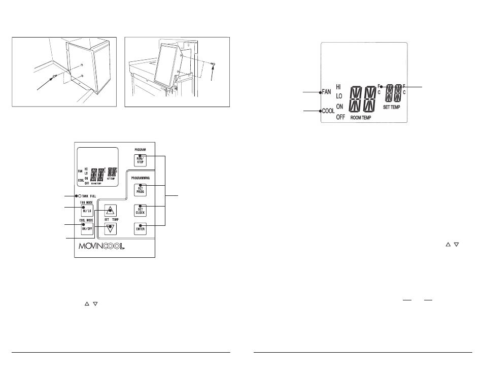
3-2. LCD indicators (See Fig. 6)
Note: ROOM TEMP display range is from 16 °F (-9 °C) to 109 °F (42 °C).
When the display value is greater than 99 °F, it displays values of +0 (for 100 °F),
+1 (for 101 °F), and +9 (for 109 °F). (This only applies to Fahrenheit values.)
6. FAN HI/LO
Illuminates to indicate selected fan speed.
7. COOL ON/OFF
Illuminates to indicate cool on or off.
8. °C or °F
Temperature displayed in either Fahrenheit or
Celsius (See Note).
7
8
6
3-3. Operating in COOL Mode
1. The unit can be operated in COOL mode by pressing the COOL ON/OFF button
(LCD indicates “COOL ON”).
Note: In COOL mode the unit can only be turned off by pressing the COOL
ON/OFF button.
2. Change the fan speed by pressing the FAN HI/LO button.
3. Change the temperature set point by pressing the SET TEMP buttons (
/
).
Note: When turning the unit on, the set point and fan speed are determined by
the last operating mode.
Fig. 6
3-4. Operating in FAN ONLY Mode
1.
The unit can also be operated in FAN ONLY mode by pressing FAN HI/LO
button (LCD indicates “FAN HI/LO” and “COOL OFF”).
2.
The unit can then be turned off by pressing the FAN HI/LO button until fan
turns off (FAN ONLY mode speed sequences are HI > LO > OFF).
3-5. Changing from FAN ONLY Mode to COOL Mode
The COOL mode can be activated while the unit is operating in FAN ONLY mode.
To do this, simply press the COOL ON/OFF button (LCD indicates “COOL ON”).
Note: The FAN ONLY mode does not operate after the COOL mode has been
activated. The unit can only be turned off by pressing the COOL ON/OFF button.
2
Screws (2)
Screws (2)
2-2. Install four (4) screws to secure the switch assembly to the stays on the unit (See
Fig. 3 and Fig. 4).
3. Operation of Switch Assembly
1.
COOL Mode Button
Activates/deactivates the COOL mode/turns the
unit off.
2.
FAN Mode Button
Activates/deactivates the high, low, and off fan
speed.
3.
SET TEMP Buttons (
/
)
Temperature scale illuminates to indicate the
current LED temperatures being displayed are
either in °C or °F.
4.
TANK FULL LED
Flashes when drain tank is full.
3-1. Before operating the unit, it is important to familiarize yourself with the basic
control functions of the switch assembly (See Fig. 5).
5.
NOT USE
These buttons are covered by the unit top cover.
Fig. 3
Fig. 4
Classic Plus 26
1
2
3
4
5
Fig. 5