Museum Technology Source KD-3 Proximity Switch User Manual
Page 3
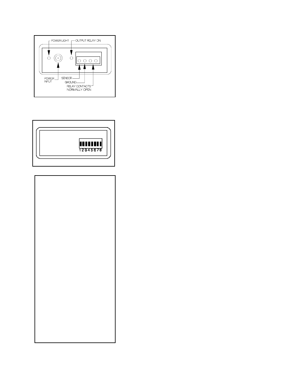
INSTALLATION
Connect the SENSOR screw terminal to the sensing plate or wire
to be used. The wire connecting the two should be kept as short
as possible to maintain sensitivity. The maximum length of the con-
necting wire is largely determined by the size of the sensor. A large
sensing plate will allow for a longer connecting wire. If a small
sensing plate is to be used with the KD-3 mounted at a distance,
coaxial cable should be used, with the shield connected to the
GROUND terminal
Connect the supplied 9 Volt DC power supply to the POWER IN
jack. Allow ten seconds or so for the KD-3 to complete its calibra-
tion cycle and then move a hand towards the sensor. When the
hand is detected, the normally open relays contacts will close, and
the red ACTIVE light will illuminate.
SETTING OPTIONS
It is well to bear in mind that each installation is to some degree dif-
ferent. Hence it is recommended that various settings be tried until
optimal operation is achieved. Please consider these instructions
to be a general outline of the KD-3’s operation, and not a set of
absolute requirements.
As supplied, all switches are in the up position. This sets the KD-3
to the default settings, which are appropriate for most applications.
The optional settings configure the KD-3 to deal with the installation
at hand. After making a new setting, briefly power off the KD-3.
Switches 1 and 2 serve to increase the sensitivity. With both in the
down position, maximum sensitivity is provided. Do not use more
sensitivity than actually required to avoid false triggering.
In situations where the hand approaches the sensor a a slow rate,
placing switch 3 in the down position will make the KD-3 more
responsive. Switch 4 provides for even slower movement, and 3
and 4 both down is for very slow motion. Be aware that using
these settings will make the KD-3 less sensitive to a fast moving
hand.
If a small sensing area is used, in the order of a few square inches,
switch 5 should be placed in the down position.
If a long wire is used to connect the sensing plate to the KD-3, or if
a large sensing plate is used, switch 6 may be helpful in maintain-
ing sensitivity.
With both switches 7 and 8 in the up (off) position, the relay will
close for approximatey 1 second and then open when a hand is
detected. Placing switch 7 down activates the pushbutton mode, in
which the relay remains on as long as the hand is within the detec-
tion range. With switch 8 down, the KD-3 is in toggle mode. The
first detection will turn the output on, and it will remain on until a
second detection occurs.
DIP SWITCH FUNCTIONS
Default is all UP
1. Increase sensitivity
2. Additional sensitivity
1 + 2. Maximum sensitivity
3. Slow moving
4. Slower moving
3+4. Slowest moving
5. Small sensor area
6. Long cable and or large sensor
7. Pushbutton mode
8. Toggle mode
Revised 11-1-2012