Installation – Museum Technology Source TDR-10 Timed Power Control User Manual
Page 2
Installation
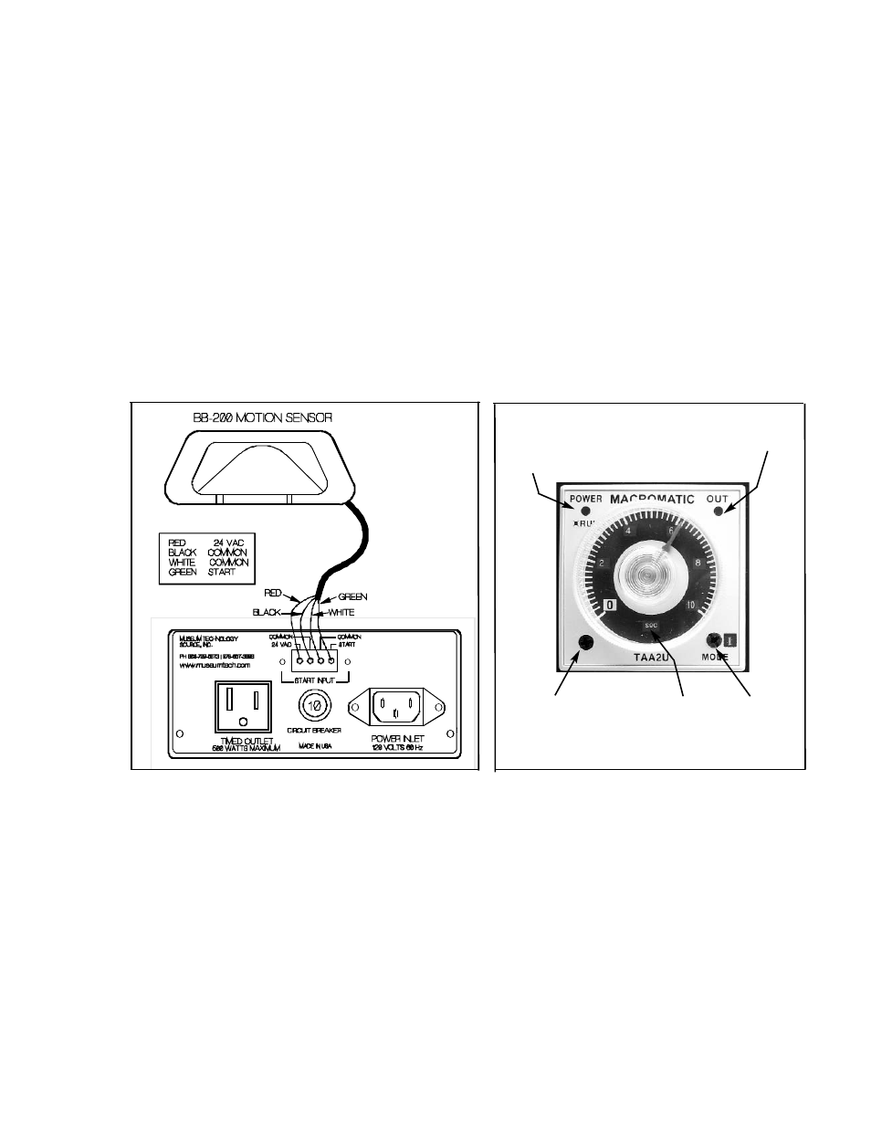
Locate the TDR-10 so as to minimize the length of the AC power cable and the cord going to the lights (or
other device) to be controlled. The drawing below shows the connections to be used if the TDR-10 is used
in conjunction with a Museum Technology BB-200 Motion Sensor. If a pushbutton or other form of nor-
mally open switch is employed it is connected between the COMMON and START screw terminals The
cable connecting the TDR-10 and the BB-200 carries only low voltage and may be any reasonable length
up to several hundred feet provided wire of at least 22 guage is used. For ease of installation, the green
screw terminal block my be disconnected from the TDR-10 by simply pulling it out.
Plug the cable from the exhibit into the TIMED OUTLET. Connect the supplied power cord to the POWER
INLET and plug the other end into a source of 120 Volts AC of sufficient capacity to operate the load.
Although ventilation is not required, the TDR-10 should remain accessible for adjustment or service.
Lights when
outlet is ON
Operation & Power LED
Steady: Timer stopped
Flashing: Timer running
Time Range
Selector
(Rotate in clock-
wise direction)
Time Units
(seconds,minutes,
hours, hours X 10
Mode Select
(Leave on I)
Setting the time
As shipped, the Time Range is set at 0 to 10 minutes. To set the time, simply rotate the knob to the desired setting. If
a shorter or longer time is needed, use a small screwdriver to rotate the TIME RANGE switch (turn clockwise) The
TIME UNITS display will change to indicate either seconds or hours. In addition, number will appear at cardinal
points on the dial indicating the new calibration ( 0, 2, 4... or 0, 20, 40 etc)
Museum Technology Source Inc.
323 Andover Street Wilmington MA 01887
800-729-6873 | 978-657-3898 | f 978-657-7132
www.museumtech.com
Rev A August 2012