NIStune Type 2 V.1.6 User Manual
Page 9
Type 2 Hardware Installation Manual
Page 9 of 20
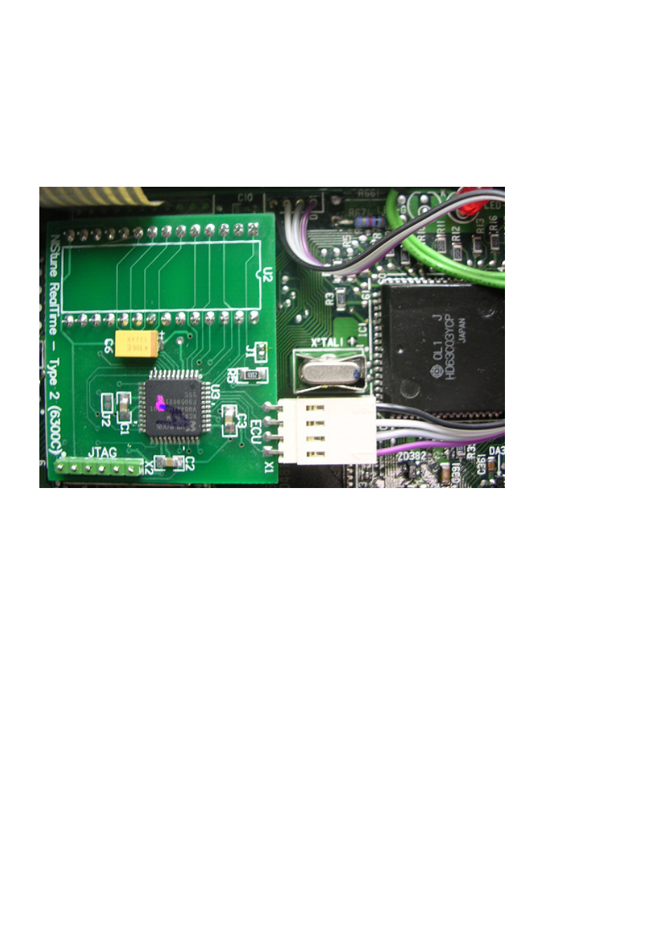
Where you have desoldered the four pads, solder in the supplied connector cable. The plastic
connector has a number '1' on it. This corresponds to pin D of the connector. Make sure that you
solder in the cable in the correct direction
Connector Wire 1 - ECU throughhole D (Marked)
Connector Wire 2 - ECU throughhole C
Connector Wire 3 - ECU throughhole B
Connector Wire 4 - ECU throughhole A
Next plug the Nistune Type 2 board into the EPROM socket. Be very careful all the pins on the
Nistune board are straight and do not bend when pushing this into the socket. Plug the ECU
connector into the Nistune board
Hot glue the corners of the board to the ECU and the connector plug. This ensures that the
board stays installed the EPROM socket and the connector does not come off when the ECU
in the vehicle endures vibration
If the board becomes dismounted or the ECU connector plug comes loose the ECU will enter limp
home mode.
Reinstall the knock sensor board, being wary of the knock sensor cable.
NOTE: Put several layers of insulation tape or foam between the knock sensor cable and the
Nistune board so that the socket pins poking through do not protrude through the knock
sensor cable.