Computer interface, Overview, Front panel – Niveo Professional NUPS20-3 User Manual
Page 5: Rear panel
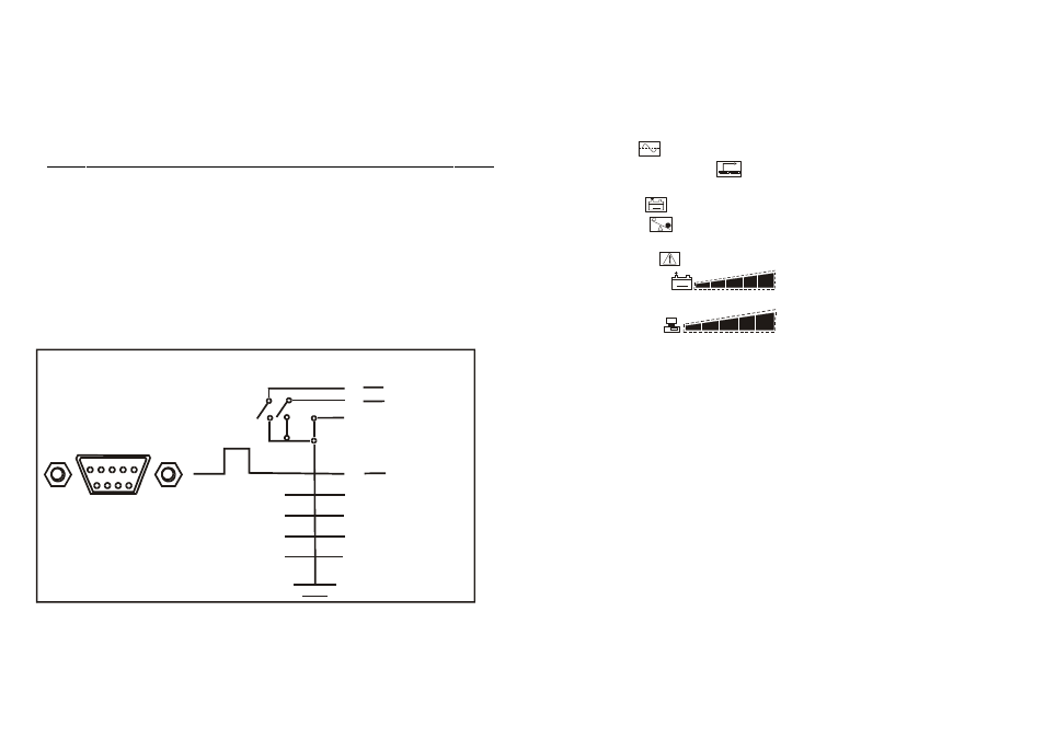
COMPUTER INTERFACE
The computer interface (DB9 port) on the back of the UPS may be
connected to a host computer. This port allows the computer to monitor the
status of the UPS and control the operation of the UPS.
Pin out information:
PIN#
Description
I/O
PIN1
PIN2
PIN3
PIN4
PIN5
PIN6
PIN7
PIN8
PIN9
Battery low, normally open, active close
N.C.
Common Ground
Remote shut down, keep this pin high
(+5~+12V) for 3S will turn off the UPS
N.C.
N.C.
Must keep in high state
Line fail, normally open, active close
N.C.
Output
Input
Input
Output
1
2
3
4
5
6
7
8
9
D-SUB 9 Pin Female Connector
Signal High Min. 3 Second
Contacts
Normally
Open
Low Battery
Mains Failure
Pin Number
UPS Shut Down
5
8
6
3
1
4
7
2
9
- 8 -
OVERVIEW
Front Panel
1. UPS Test Switch :
When UPS is working under AC mode, it also activates
the UPS`s self-test by press the bottom.
2. Master Power Switch :
Turn on/off the UPS.
3. LINE-ON(
)
:
AC Normal
.
4. AVR Protection LCD(
)
:
When AVR is working under protection mode,
the light will turn on.
5. BACK-UP(
-
)
:
Battery in back-up
6. Over Load(
)
:
If the UPS is overloaded, the light will turn on and the alarm
will sound continuously.
7. UPS Cut-off(
)
:
Overload or Cut-off
8. Battery Level(
-
)
:
A bar graph showing how much of the
UPS battery is being used.
9. Load Level(
)
:
A bar graph showing how much of the
UPS power is being used.
Rear Panel
1. AC line input socket :
Connect power cable from the UPS to AC utility.
2. AC input fuse :
Contain the fuse to protect the UPS from over current
from incoming AC utility.
3. Output receptacles :
Connect power cables of computer equipment to this sockets.
4. Computer interface :
This socket combines relay contact signals DB9 connector.
5. Phone/Fax/Modem jack :
Telecom transfer ports provide users to extend the
applications.
6. USB port:
Communication port.
7. UPS setup switch:
Dip1.
Low load auto shutdown: OFF.
Low load (below 50W) auto shutdown: ON.
Dip2.
DC-Start: ON.DC-Start: OFF.
Dip3.
Buzzer auto-reset: (UPS continue buzzing under backup mode.)
Buzzer auto-reset: (To adjust the switch down to silence the
audible alarm when
UPS is under backup model. But, the function is disabled when UPS is under
cond
ition of “Battery low”)
8. EXT.BATTERY:
Connect external battery cable for battery bank to the UPS.
- 5 -