1 headset volume and sensitivity adjustments, 2 auxiliary receive control(s), 3 mode control (aa38-5xx and -6xx) – Northern Airborne Technology AA38-5xx User Manual
Page 13
AA38-5xx, -6xx, -7xx and -8xx Series Local ICS Loop
SM54 Installation and Operation Manual
Section 2 Rev: 1.00
Issue 4
Page 2-4
2.5.1
Headset Volume and Sensitivity Adjustments
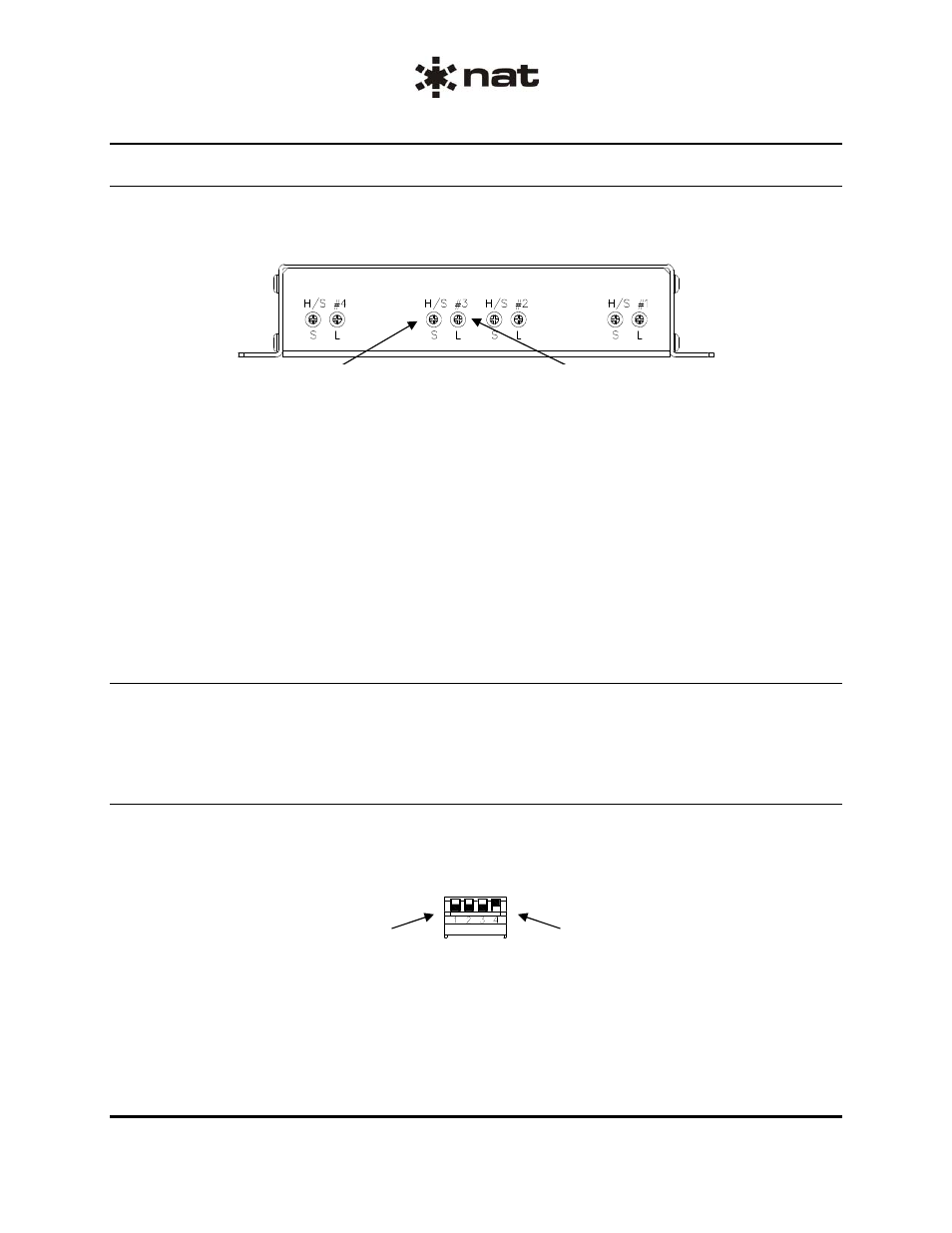
The headset volume and sensitivity controls are located on the rear of the unit as shown in Figure 1
below. Each headset position has a level trimpot (L) and a sensitivity trimpot (S) that controls MIC/VOX
operation.
ENG-FORM: 805-0115.DOT
CONFIDENTIAL AND PROPRIETARY TO NORTHERN AIRBORNE TECHNOLOGY LTD.
Headset #3 Level (Volume) Adjustment
Headset #3 Sensitivity Adjustment
Figure 1: Headset Volume and Sensitivity Controls
The AA38-502, AA38-602 and AA38-802 have two banks of controls. The individual headset level
(volume) controls provide up to 40 dB of dynamic range. For maximum headset power rotate the pot fully
clockwise (cw) and for minimum headset power rotate fully counter-clockwise (ccw).
The individual sense control trimpots are used to select the required operating mode for the headsets. For
KEYED ICS (PTT operation) the trimpot is set fully cw. For LIVE (Hot MIC operation) the trimpot is set
fully ccw. For VOX (Voice Activated operation) the trimpot is set in the mid position.
To obtain the best setting for the ambient noise conditions and the quality and number of MICs connected
in the system, set the trimpot fully ccw, then slowly rotate it cw until the intercom just becomes ‘quiet’.
Check this setting for both ground and flight operation.
2.5.2
Auxiliary Receive control(s)
The Auxiliary (AUX) receive (RX) level trimpot (RX LEVEL) is located on the front of the unit, and provides
up to 40 dB of dynamic range. When rotated fully cw it gives maximum AUX RX input level, and fully ccw
gives minimum level. The AA38-502, AA38-602 and AA38-802 have two of these controls.
2.5.3
Mode Control (AA38-5xx and -6xx)
The Mode Control switch is used for selecting the type of ICS tie line configuration required and is a quad
piano DIP-switch accessible through the left side of the unit. To open a switch, place it in the ‘up’ position
and to close it put it in the ‘down’ position as shown in Figure 2.
Switches 1, 2 and 3 shown in the
closed (down) position.
Switch 4 shown in the open
(up) position.
Figure 2: Mode Control DIP Switch